Siemens SINUMERIK 840C User Manual
Page 654
09.95
Siemens AG 2001
All Rights Reserved
6FC5197–
j
AA50
9–33
SINUMERIK 840C (IA)
9.4
Mixed I/O configuration and digital-analog converter, DAC (as
from SW 3)
General notes on
The possible applications for digital-analog converters described in this Section
mixed I/O
are used to conduct test measurements on digital signals from the drive or posi-
tion control. These signals can be output as analog voltages for diagnostic purpo-
ses on an oscilloscope or a recorder.
The 4 DAC channels of the MIXED I/O module with the order no.
6FX1138–4BA01 (16-bit resolution) are used for this purpose.
The DAC signals are output at connector X111.
General notes
Max. 4 DAC channels are supported for output of SERVO quantities.
on DAC, 611D drives
The DACs on the 611D feed and main spindle drives have the following features:
SW 3:
S
8-bit resolution
S
3 DACs on each feed drive module (single and two-axis module).
S
Each main spindle module is provided with 2 DACs and a special-purpose
test socket. This test socket outputs a voltage which is proportional to the cur-
rent actual value of phase R (see Table).
Module
Scaling
Test socket I
R
8/10/16 A
25 A
8
8.25 V
24/32/32 A
50 A
8
8.25 V
30/40/51 A
75 A
8
8.25 V
45/60/76 A
150 A
8
8.25 V
60/80/102 A
150 A
8
8.25 V
85/110/127 A
200 A
8
8.25 V
SW 4/SW 5:
S
8-bit resolution
S
3 DACs are installed on each MSD and FDD module
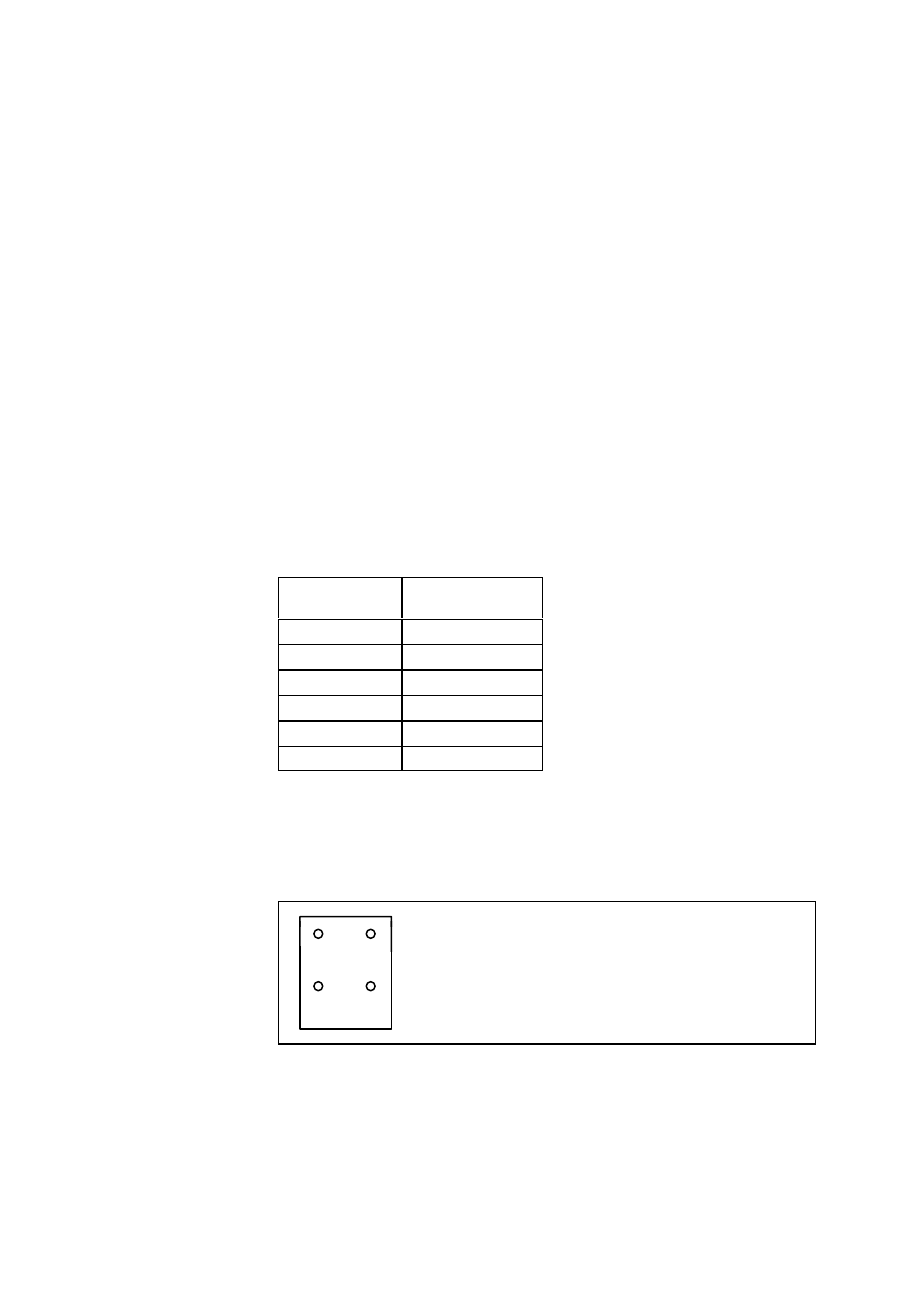
Arrangement of DACs/sockets:
X1 :
Test socket DAC1
X2 :
Test socket DAC2
X2
X1
X3 :
Test socket DAC3
X3/I
R
M
I
R
:
Test socket current actual value phase R
(MSD module) – SW 3 only
X3/I
R
M
M :
Reference earth for test sockets
With SW 3 only, the scaling of the voltage output with test socket I
R
is dependent
on the MSD module used:
9 Drive Servo Start-Up Application (as from SW 3)
9.4 Mixed I/O configuration and digital-analog converter, DAC (as from SW 3)