Siemens SINUMERIK 840C User Manual
Page 1003
12 Functional Descriptions
09.95
12.20.8 Configuration help for generator operation and emergency retraction
Example:
C
=
6000
µ
F (see table 16 kW infeed/regenerative feedback module) - 20%
U
Zk
=
550 Volt (P1634)
U
min
=
350 Volt (assumed)
E
=
1/2 * 4800
µ
F * ((550 V)
2
- (350 V)
2
) = 432 Ws
This energy is available at load for a time of:
t
min
=
E/P
max
*
where
t
min
=
backup time in milliseconds [ms]
P
max
=
power in kilowatts [kW]
=
degree of efficiency of the drive unit = 0.90
Example:
E
=
432 Ws
P
max
=
16 kW (see table for 16 kW infeed/regenerative feedback module)
=
0.90
t
min
=
432 Ws/16 kW * 0.9 = 24.3 ms
in order to initiate the emergency retraction.
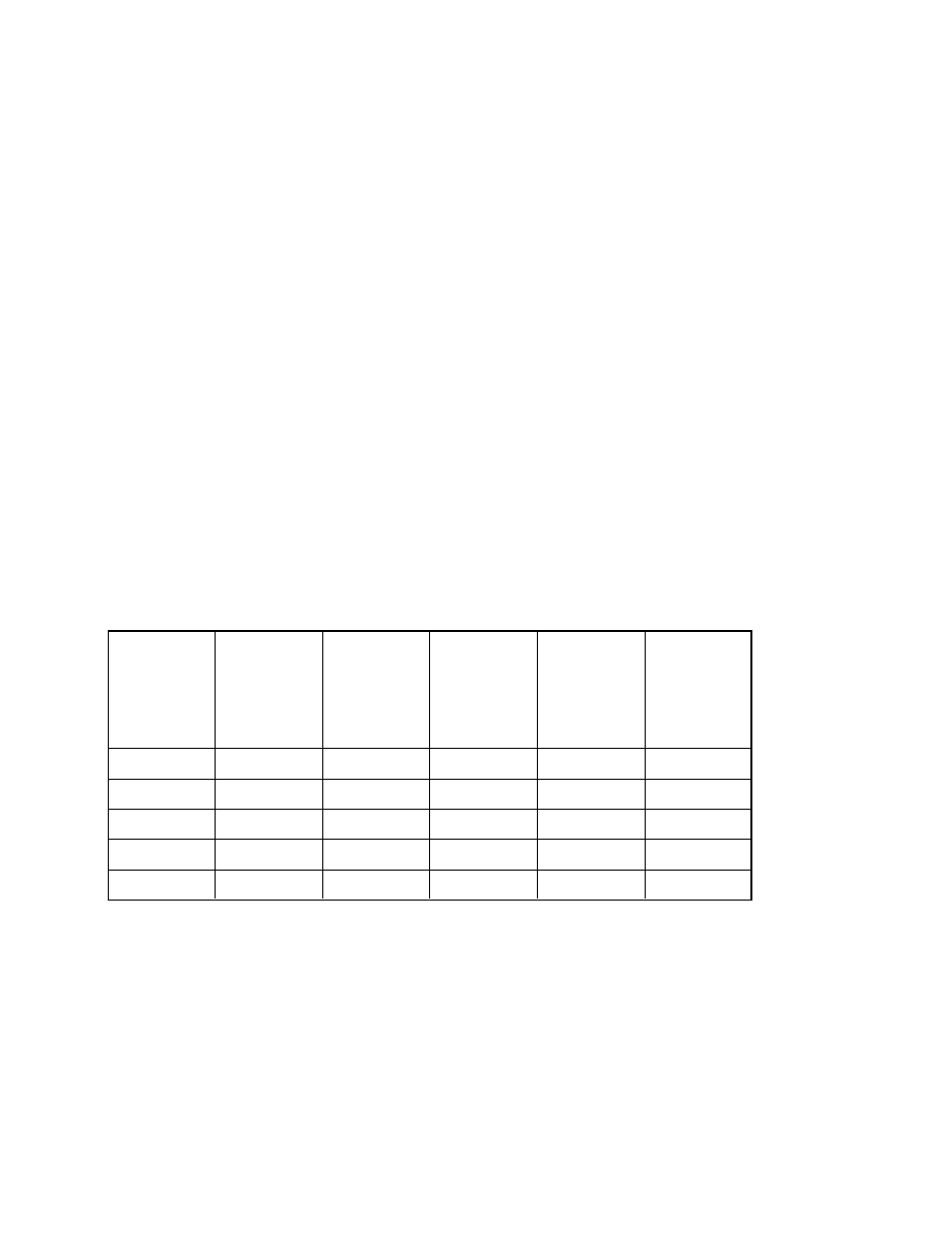
The table below shows a summary of the values for different infeed/regenerative feedback
units. Nominal and minimum capacitances have been taken into account. The maximum
possible capacitance (load limit) consists of the sum of the capacitances of the
infeed/regenerative feedback module and the axis/spindle modules plus additional external
capacitors (provided by the customer). The minimum capacitance shown in the table takes
account of a component tolerance of -20% (worst case).
Infeed/regen-
erative
feedback unit
(power P
max
)
[kW]
Max. possible
capacitance
C
max
[
µ
F]
Energy
content (at
C
max
) [Ws]
Energy
content (at
C
min
) [Ws]
Backup time
t
n
at P
max
[ms]
Backup time
t
min
at P
max
[ms]
16
6000
540
432
30.38
24.30
36
20000
1800
1440
45.00
36.00
55
20000
1800
1440
29.46
23.56
80
20000
1800
1440
20.25
16.20
120
20000
1800
1440
13.50
10.80
Note:
In configuring the emergency retraction, a total energy must be calculated to find out if it is
possible to eliminate an additional generator axis/spindle (with an appropriately dimensioned
centrifugal mass).
12–228
© Siemens AG 1992 All Rights Reserved 6FC5197- AA50
SINUMERIK 840C (IA)