Dl 121, Dr 121, Dl 125 – Siemens SINUMERIK 840C User Manual
Page 1014: Dr 125, Dl 237, Dr 237
12.93
12 Functional Descriptions
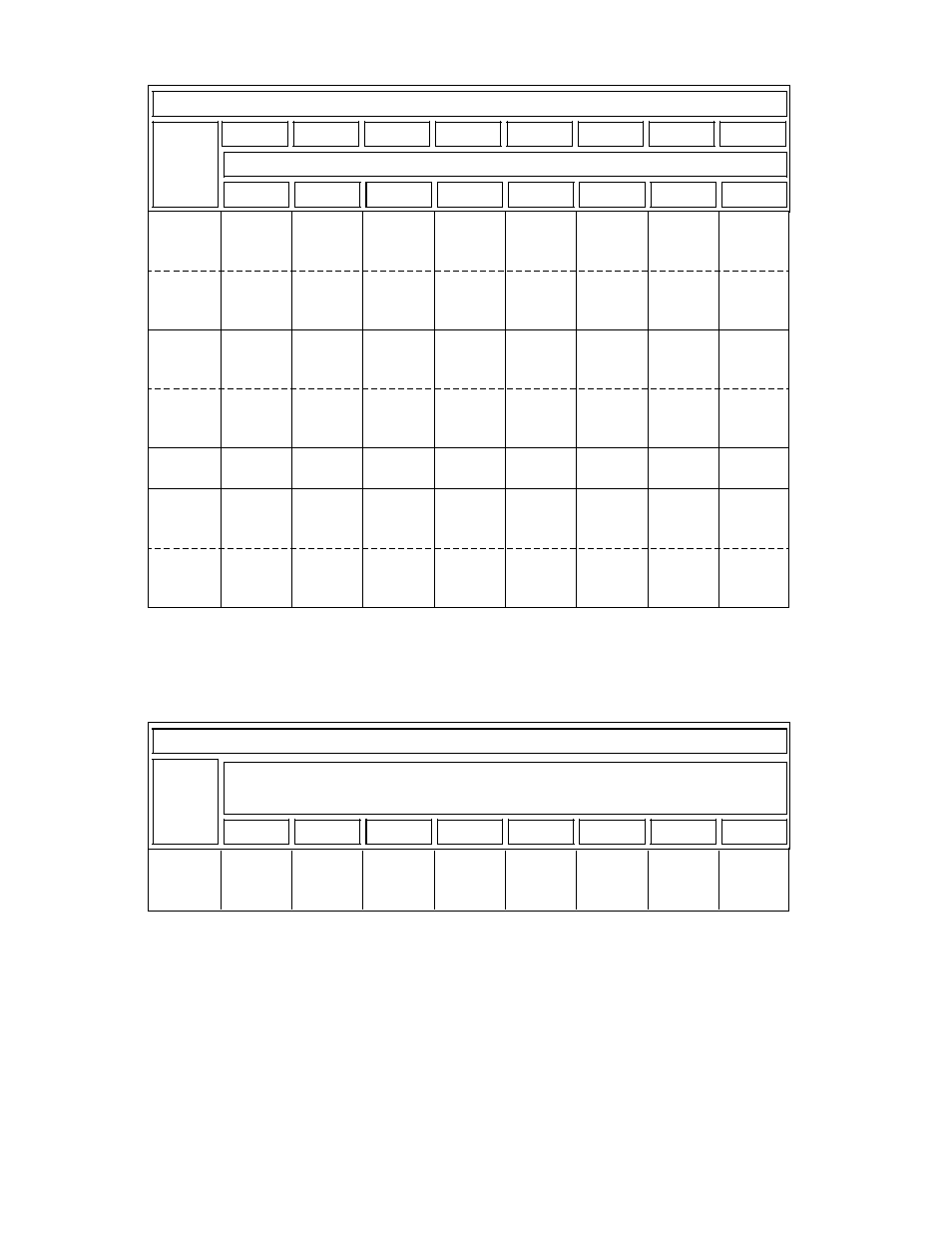
12.22.2 Functional description
7
6
5
4
3
2
1
0
Bit No.
Byte no.
Axis1
DL
121
Cam
4+
Cam
4–
Cam
3+
Cam
3–
Cam
2+
Cam
2–
Cam
1+
Cam
1–
Axis1
DR
121
Axis2
DL
125
Cam
4+
Cam
4–
Cam
3+
Cam
3–
Cam
2+
Cam
2–
Cam
1+
Cam
1–
Axis2
DR
125
:
:
Axis30
DL
237
Cam
4+
Cam
4–
Cam
3+
Cam
3–
Cam
2+
Cam
2–
Cam
1+
Cam
1–
Axis30
DR
237
Signals from axis
15
14
13
12
11
10
9
8
The user can also output the cam signals in the IPO cycle via a digital output byte of the
MIXED I/O. The cam signals are assigned to a MIXED I/O output byte via NC MD 311.
7
6
5
4
3
2
1
0
Bit No.
Byte No.
1 or 2
Cam
4+
Cam
4–
Cam
3+
Cam
3–
Cam
2+
Cam
2–
Cam
1+
Cam
1–
MIXED I/O
© Siemens AG 1992 All Rights Reserved 6FC5197- AA50
12–239
SINUMERIK 840C (IA)
This manual is related to the following products: