Setting data for pcf files – Siemens SINUMERIK 840C User Manual
Page 127
09.95
Siemens AG 2001
All Rights Reserved
6FC5197–
j
AA50
4–64
SINUMERIK 840C (IA)
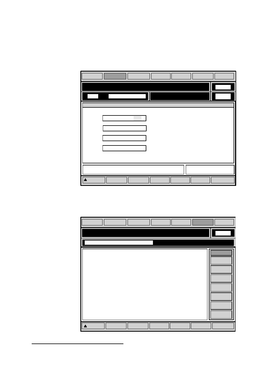
Setting data for PCF files:
You define the active PCF file in the general setting data.
The setting data are described in the Operator’s Guide.
DryĆrun feedrate
F
=
0
Incremental value for INC variable
INCĆvar.
=
50
Smoothing constant for thread cutting
T
= 0
PLC alarm text file
PCF 3
1)
16:38
JOG
PROGRAM RESET
BAG
:1
Kanal
:1
General data
Work area
limitation
General
data
Spindle
data
Scale
General
bits
Axial
bits
Cycle
data
MACHINE
PARAMETER PROGRAMM.
SERVICES DIAGNOSIS
Fig. 4.28
SW 1
Example
PCF file
N6000
(CLOSE DOOR) L
F
N6005
(LUBRICANT MIN REACHED!) L
F
N6010
(TOOL BREAK) LF
N6015
(HYDRAULIC OIL MIN REACHED) L
F
N6020
(OIL FILTER DIRTY) LF
N7000
(SWITCH ON MAIN DRIVE !!!) L
F
N8000
(DRIVE OF X AXIS DEFECTIVE) L
F
N9000
(SERVO ENABLE FOR Y AXIS MISSING) L
F
N9005
(FAN FAILURE !!!) L
F
N9010
(LOADER 1 DEFECTIVE) L
F
M30 L
F
SAVE
09:22
Start-up/Edit PLC data
Insert/
overwrite
Cut to
clipboard
Copy to
clipboard
Search
Paste from
clipboard
Undo
>>
PCF1
MACHINE
PARAMETER PROGRAMM.
SERVICES DIAGNOSIS
Fig. 4.29
ASCII editor with PCF 1 file
4 MMC Area Diagnosis
4.8.3 PCF files (up to SW 2)
1) Not in SW 1