MITSUBISHI ELECTRIC FR-S520E User Manual
Page 15
5
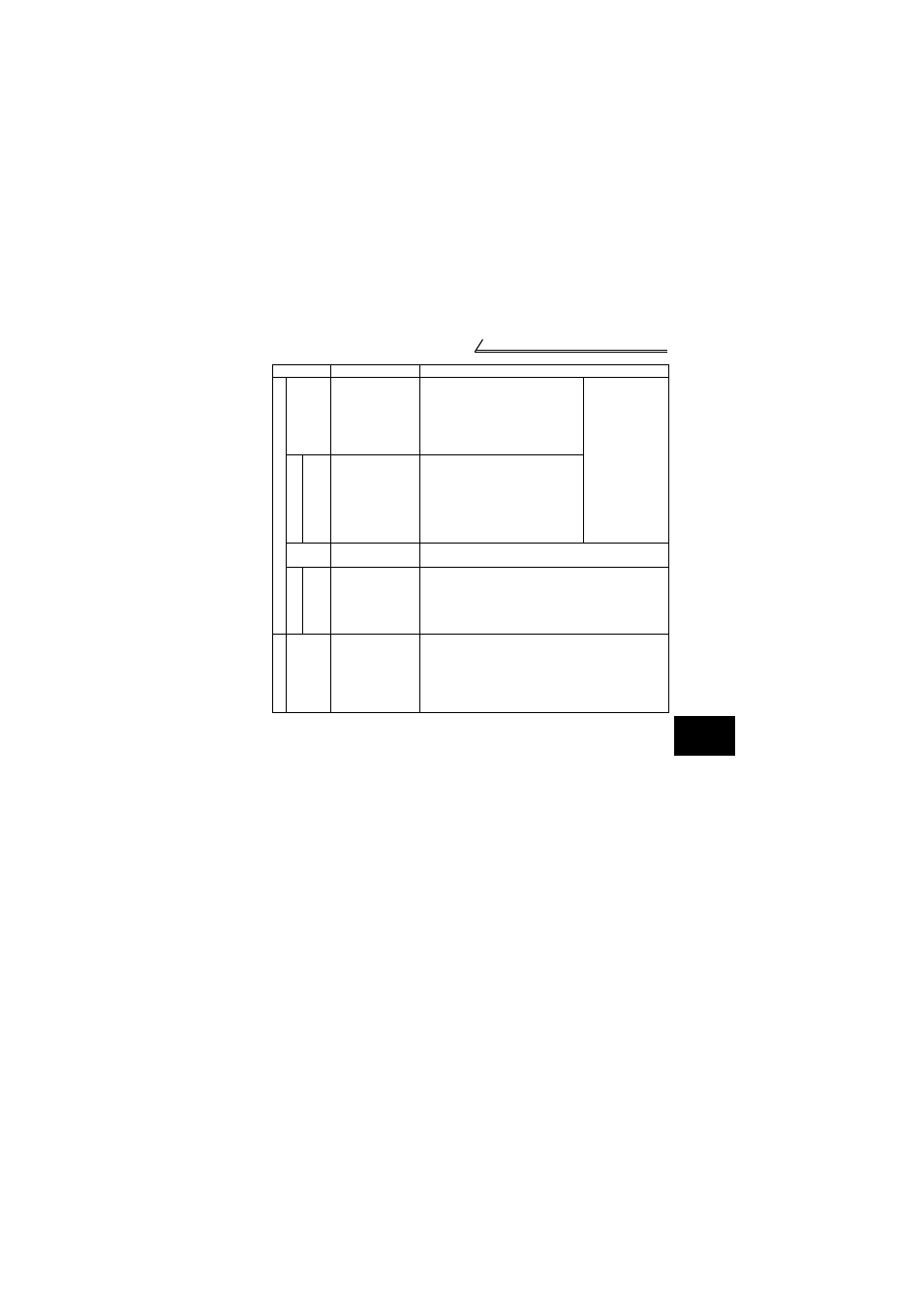
Standard connection diagram and terminal specifications
1
WI
RING
*1. Do not connect terminals SD and PC each other or to the earth (ground).
For sink logic (factory setting), terminal SD acts as the common terminal of contact input.
For source logic, terminal PC acts as the common terminal of contact input. (Refer to
page 26 for switching method.)
*2. Low indicates that the open collector output transistor is on (conducts). High indicates
that the transistor is off (does not conduct).
*3. RL, RM, RH, RT, AU, STOP, MRS, OH, REX, JOG, RES, X14, X16, (STR) signal
selection (Refer to page 102.)
*4. RUN, SU, OL, FU, RY, Y12, Y13, FDN, FUP, RL, Y93, Y95, LF, ABC signal selection
(Refer to page 104.)
*5. To be compliant with the European Directive (Low Voltage Directive), the operating
capacity of relay outputs (A, B, C) should be 30VDC 0.3A.
*6. Terminals SD, SE and 5 are isolated from each other. Do not earth (ground).
O
u
tput s
igna
ls
A
B
C
Alarm output
Changeover contact output indicates
that the inverter protective function has
activated and the output stopped.
230VAC 0.3A, 30VDC 0.3A. Alarm:
discontinuity across B-C (continuity
across A-C), Normal: continuity across
B-C (discontinuity across A-C).(*5)
The function of the
terminals changes
according to the
output terminal
function selection
(Pr. 64, Pr.65).
(*4)
O
p
en c
o
lle
ctor
RUN
Inverter
running
Switched low when the inverter output
frequency is equal to or higher than the
starting frequency (factory set to 0.5Hz
variable). Switched high during stop or
DC injection brake operation. (*2)
Permissible load 24VDC 0.1A (a
voltage drop is 3.4V maximum when
the signal is on)
SE
Open collector
common
Common terminal for inverter running terminal RUN. (*6)
Indi
cato
r
FM For meter
The output signal across terminals FM-SD is factory set to about
1mA at 60Hz and is proportional to the corresponding output
frequency. Since output voltage is pulse shape, a digital meter
can be connected.
Frequency permissible load current 1mA
Pulse specification 1440 pulses/s at 60Hz
Com
m
u
n
ica
tion
——
RS-485
connector
Using the parameter unit connection cable (FR-CB201 to
205), the parameter unit (FR-PU04) can be connected.
Communication operation can be performed using RS-485.
For details of RS-485 communication, refer to page 47.
Symbol
Terminal Name
Definition