1 electronic gear setting examples – Yaskawa Sigma II Indexer User Manual
Page 86
Sigma II Indexer User’s Manual
Setting up the Reference Units
5-31
Electronic gear ratio
=
Note: Make sure the electronic gear ratio satisfies the following condition:
0.01
d Electreconic gear ratio
d100
The servo amplifier will not work properly if the electronic gear ratio exceeds this range. In
that case, modify either the load configuration or the reference unit.
6. Set the parameters.
Reduce the electronic gear ratio to the lower terms so that both A and B are
integers smaller than 65535, then set A and B in the respective parameters:
• B = [(Number of encoder pulses) x 4] x [motor speed]
• A = [Travel distance per load shaft revolution (reference units)]
u
[load shaft
revolution speed]
5.5.1 Electronic Gear Setting Examples
The following examples show electronic gear settings for different load
mechanisms.
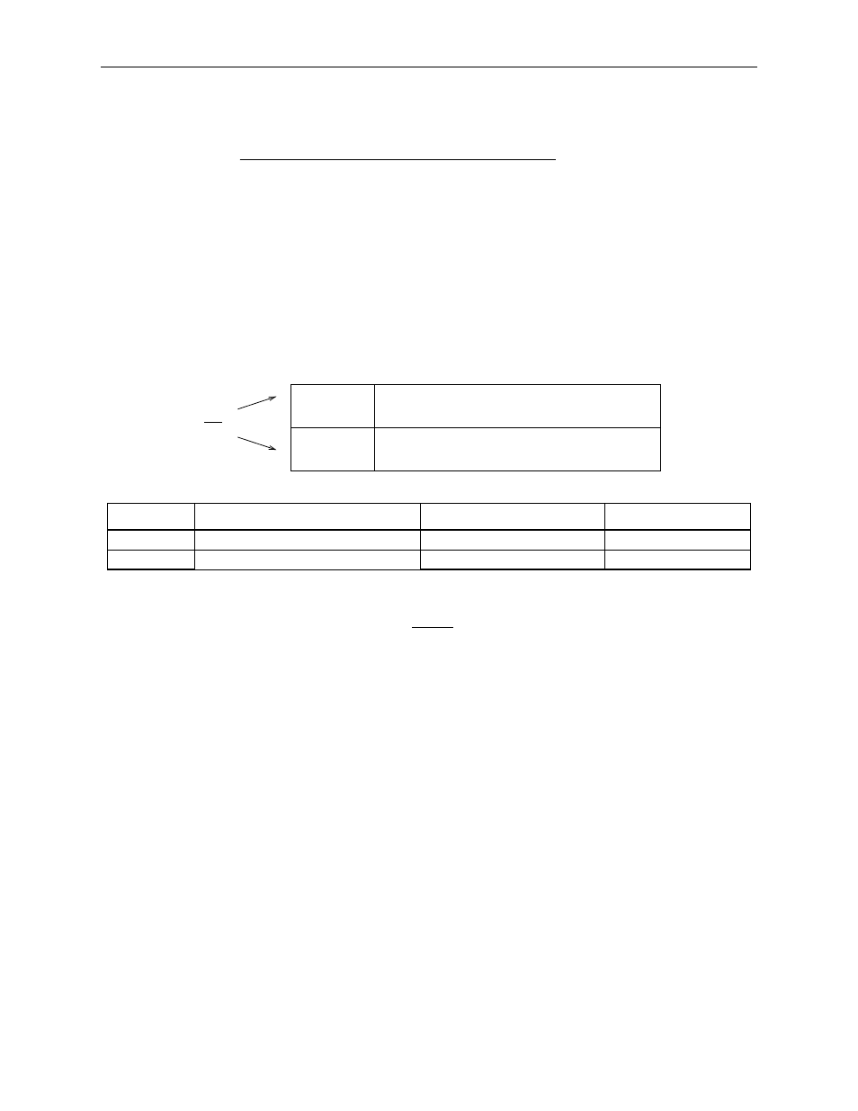
Parameter
Signal
Setting
Default
Pn202
Electronic Gear Ratio (Numerator)
Range: 1 to 65535
4
Pn203
Electronic Gear Ratio (Denominator)
Range: 1 to 65535
1
B
A
----
© ¹
§ ·
Number of encoder pulses
u
4
Travel distance per load shaft revolution (reference unit)
u
N
2
N
1
------
B
A
----
© ¹
§ ·
B
A
( )
Pn202
Pn203
Electronic Gear Ratio (Numerator)
Electronic Gear Ratio (Denominator)
Electronic gear ratio = =
B
A
----
© ¹
§ ·
Pn202
Pn203