Yaskawa Sigma II Indexer User Manual
Page 63
Sigma II Indexer User’s Manual
Settings According to Device Characteristics
5-8
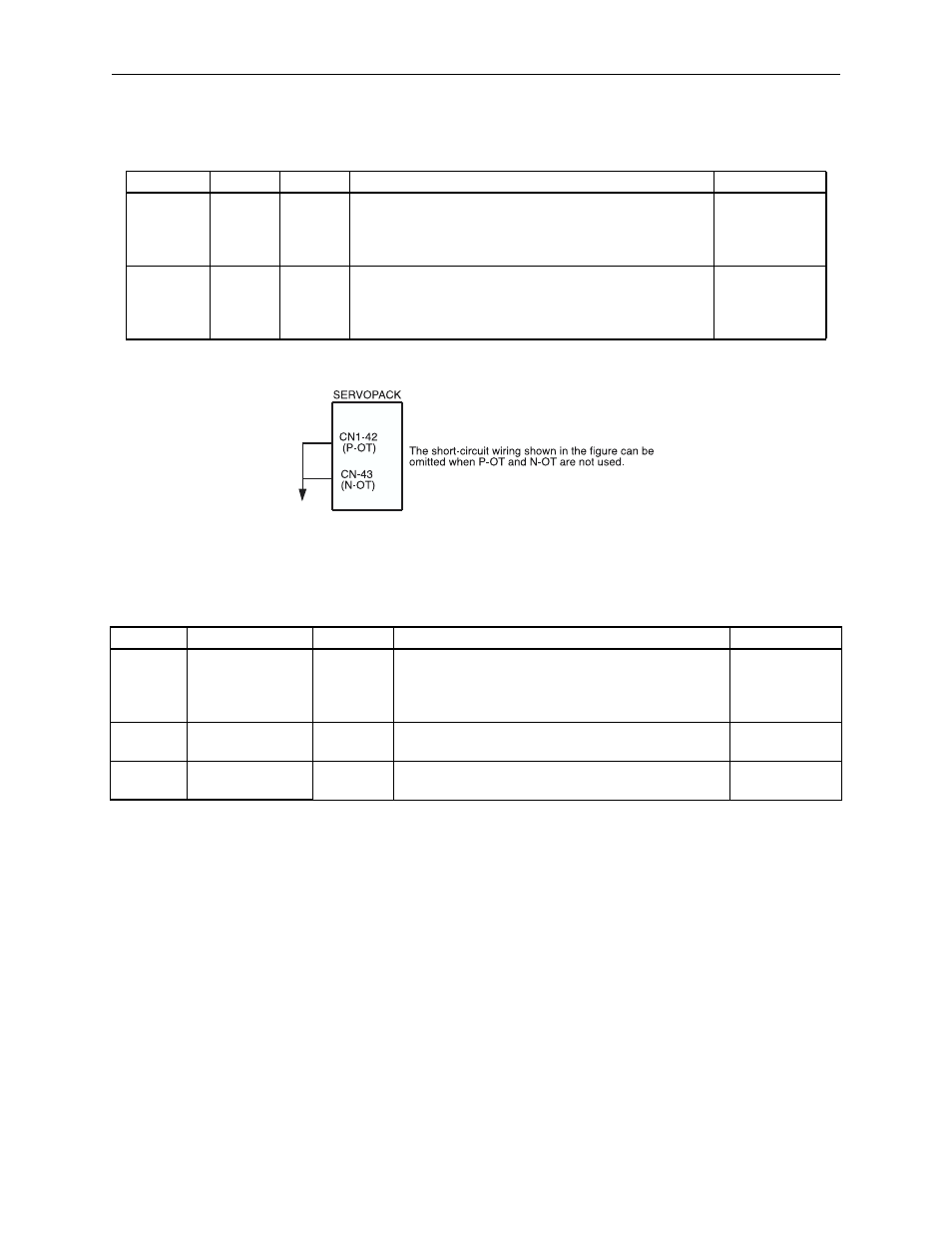
Set the following parameters to specify whether or not the input signals are used for
overtravels. The factory setting is that the input signals are used for overtravels.
Figure 5.2 Hardware Overtravel Short-Circuiting
Using the Software Position Limits
Set the following parameters to specify the software position limits.
Moving Method Settings
1. Pn81A=0=Linear:
An error will occur if commanded position is beyond forward or reverse position ref-
erence limits. Motor will not move. If motor reaches the software limits while jogging,
motor will decelerate to a stop at the deceleration rate set in Pn820. Disable the soft-
ware limits by setting both the forward and reverse position reference limits to 0.
The software limits are ignored until homing is complete when a homing routine is
specified for an incremental encoder. Refer to 5.11.3 Homing Routine Parameters for
more information regarding homing.
2. Pn81A=1=Rotary (Shortest Path): Used for rotary motion.
Absolute move commands rotate in the direction of the shortest path of travel.
Parameter
Signal
Pin No.
Setting
Default
Pn80C
P-OT CN1-42
0 = Input Signal Open = OT Status, Forward Run Prohibited
1 = Input Signal Closed = OT Status, Forward Run Prohibited
2 = Always OT Status, Forward Run Prohibited
3 = Forward Run Always Allowed
0
Pn80D
N-OT CN1-43
0 = Input Signal Open = OT Status, Reverse Run Prohibited
1 = Input Signal Closed = OT Status, Reverse Run Prohibited
2 = Always OT Status, Reverse Run Prohibited
3 = Reverse Run Always Allowed
0
Parameter
Name
Unit
Setting
Default
Pn81A
Moving Method
-
0 = Linear
1 = Rotary (Shortest Path)
2 = Rotary (Forward Rotation)
3 = Rotary (Reverse Rotation)
0
Pn81B
Position Reference
Forward Limit
Reference
Unit
- 99999999 ~ + 99999999
+99999999
Pn81C
Position Reference
Reverse Limit
Reference
Unit
-99999999 ~ + 99999999
-99999999
OV