2 i/o signals connector (cn1, cn4) – Yaskawa Sigma II Indexer User Manual
Page 31
Sigma II Indexer User’s Manual
I/O Signals (CN1, CN4)
3-4
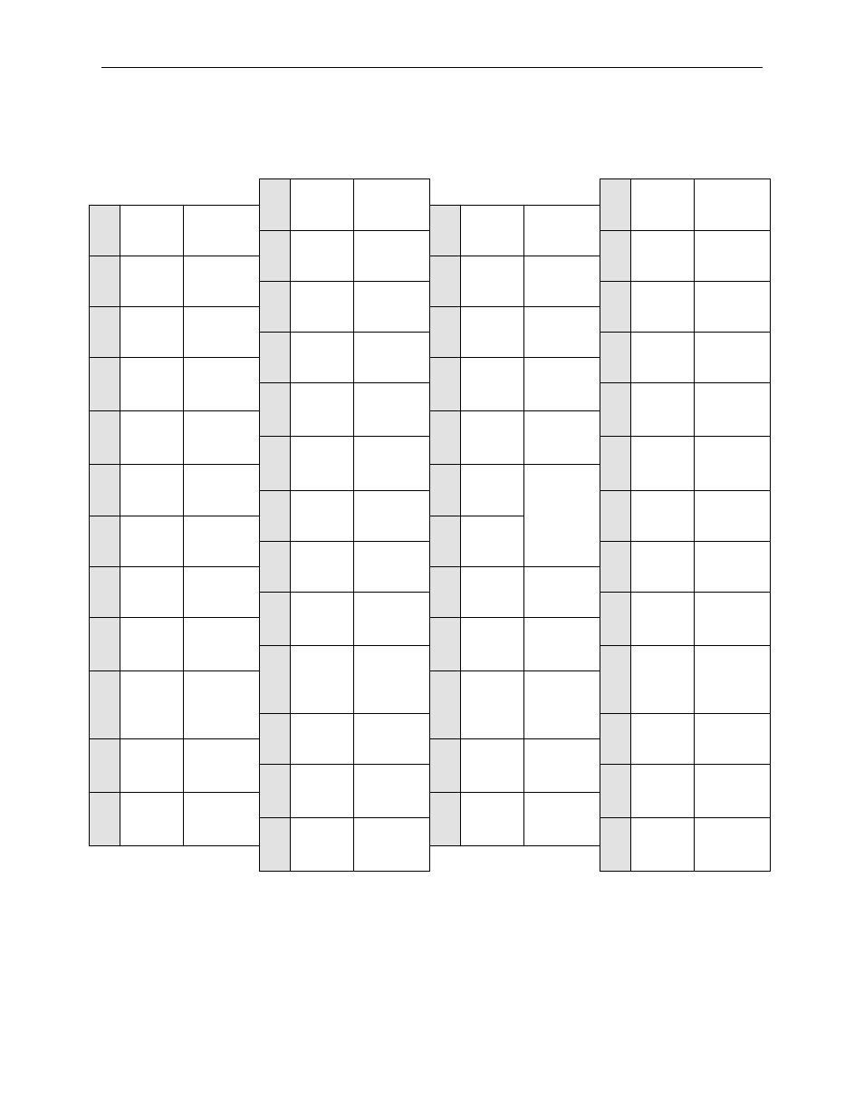
3.1.2 I/O Signals Connector (CN1, CN4)
The following diagrams show the layout of CN1 and CN4 terminals.
Table 3.1: CN1 Terminal Layout (Servo Amplifier)
Note
1.
Do not use unused terminals for relays.
2.
Connect the shield of the I/O signal cable to the connector shell.
The shield is connected to the FG (frame ground) at the servo amplifier-end connector.
1
SG
Signal
Ground
26
/WARN-
Servo warn-
ing output
2
SG
Signal
Ground
27
/BK+
Brake inter-
lock output
3
-
-
28
/BK-
Brake inter-
lock output
4
-
-
29
/S-RDY+
Servo ready
output
5
-
-
30
/S-RDY-
Servo Ready
Output
6
SG
Signal
Ground
31
ALM+
Servo alarm
output
7
-
-
32
ALM-
Servo alarm
output
8
-
-
33
PAO
PG Divided
Output
A-Phase
9
-
-
34
/PAO
PG Divided
Output
A-Phase
10
SG
Signal
Ground
35
PBO
PG Divided
Output
B-Phase
11
-
-
36
/PBO
PG Divided
Output
B-Phase
12
-
-
37
AL01
Alarm code
output
(open-
collector
output)
13
-
-
38
AL02
Alarm code
output
14
-
-
39
AL03
15
-
-
40
/S-ON
Servo ON
input
16
-
-
41
/SEL5
Program
select 5
17
-
-
42
P-OT
Forward
drive prohib-
ited input
18
-
-
43
N-OT
Reverse run
prohibited
input
19
PCO
PG Divided
Output
C-Phase
44
/DEC
Zero point
return decel-
eration LS
input
20
/PCO
PG Divided
Output
C-Phase
45
/SEL6
Program
select 6
21
BAT (+)
Battery (+)
46
/RGRT
Registration
latch
22
BAT (-)
Battery (-)
47
+24VIN
External
power sup-
ply input
23
-
-
48
PSO
S-Phase
Signal
Output
24
-
-
49
/PSO
S-Phase
Signal
Output
25
/WARN+
Servo warn-
ing output
50
-
-