5 setting up the reference units – Yaskawa Sigma II Indexer User Manual
Page 84
Sigma II Indexer User’s Manual
Setting up the Reference Units
5-29
5.5
Setting up the Reference Units
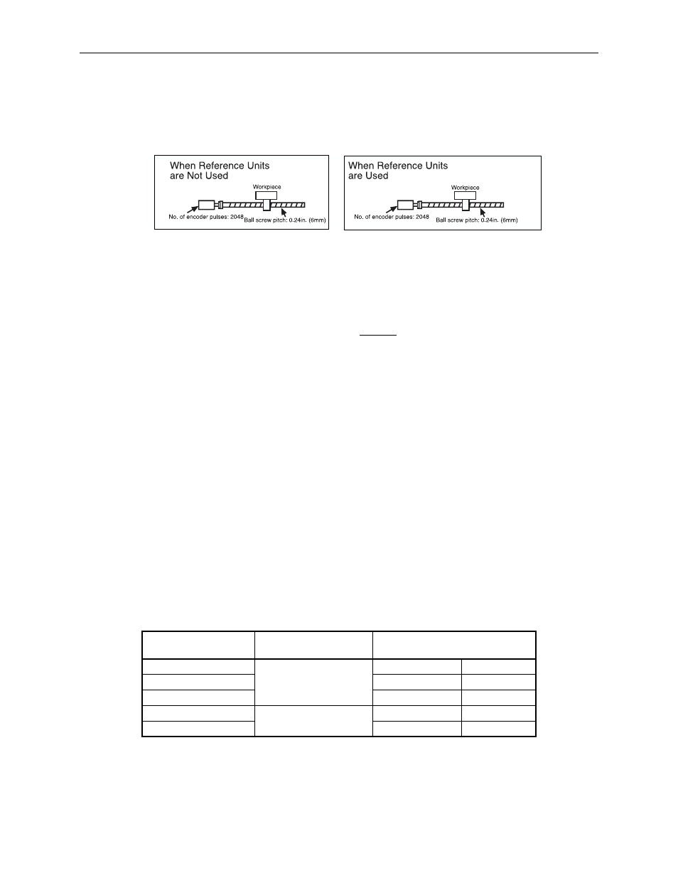
The Sigma II Indexer stores all positioning data in units of [Reference Units].
Reference units allow the user to program in terms of load (or workpiece) travel dis-
tance instead of servomotor travel distance.
Setting the Reference Units
Set the reference units by calculating the electronic gear ratio (B/A) using the fol-
lowing procedure, and set the values in parameters Pn202 and 203.
1. Check equipment specifications related to the reference units:
• Speed Reduction Ratio, N
2
:N
1
N
1
= rotation of the load shaft
N
2
= rotation of the motor
• Ball screw pitch
• Pulley diameter
2. Check the number of encoder pulses for the SGM
H servomotor.
Note: The number of bits representing the resolution of the applicable encoder is not the same as the num-
ber of encoder signal pulses (A and B phase) output from the servo amplifier.
Servomotor Model and
Encoder Specifications
Encoder Type
Number of Encoder Pulses Per Revo-
lution (p/rev) (“pre-quadrature”)
A
Incremental encoder
13–bit 2048
B
16–bit
16384
C
17–bit
32768
1
Absolute encoder
16–bit
16384
2
17–bit
32768
Reference unit: 1
Pm
To move a workpiece 0.39in. (10mm):
1 revolution = 6mm. Therefore,
10 ÷ 6 = 1.6667 revolutions.
(2048
u 4) pulses = 1 revolution. So,
(1.6667
u 2048 u 4) = 13653 pulses
13563 pulses are input as the reference.
To move a workpiece 0.39in. (10mm):
units must be defined in the servo
Equipment conditions and reference
units
10mm
1
Pm
10000 reference
Reference unit is 1
Pm. Therefore,
amplifier beforehand.