3 i/o signal names and functions, Table 3.4: cn4 specifications (sigma ii indexer), Table 3.5: cn1 input signals (servo amplifier) – Yaskawa Sigma II Indexer User Manual
Page 33: Table 3.6: cn1 output signals (servo amplifier)
Sigma II Indexer User’s Manual
I/O Signals (CN1, CN4)
3-6
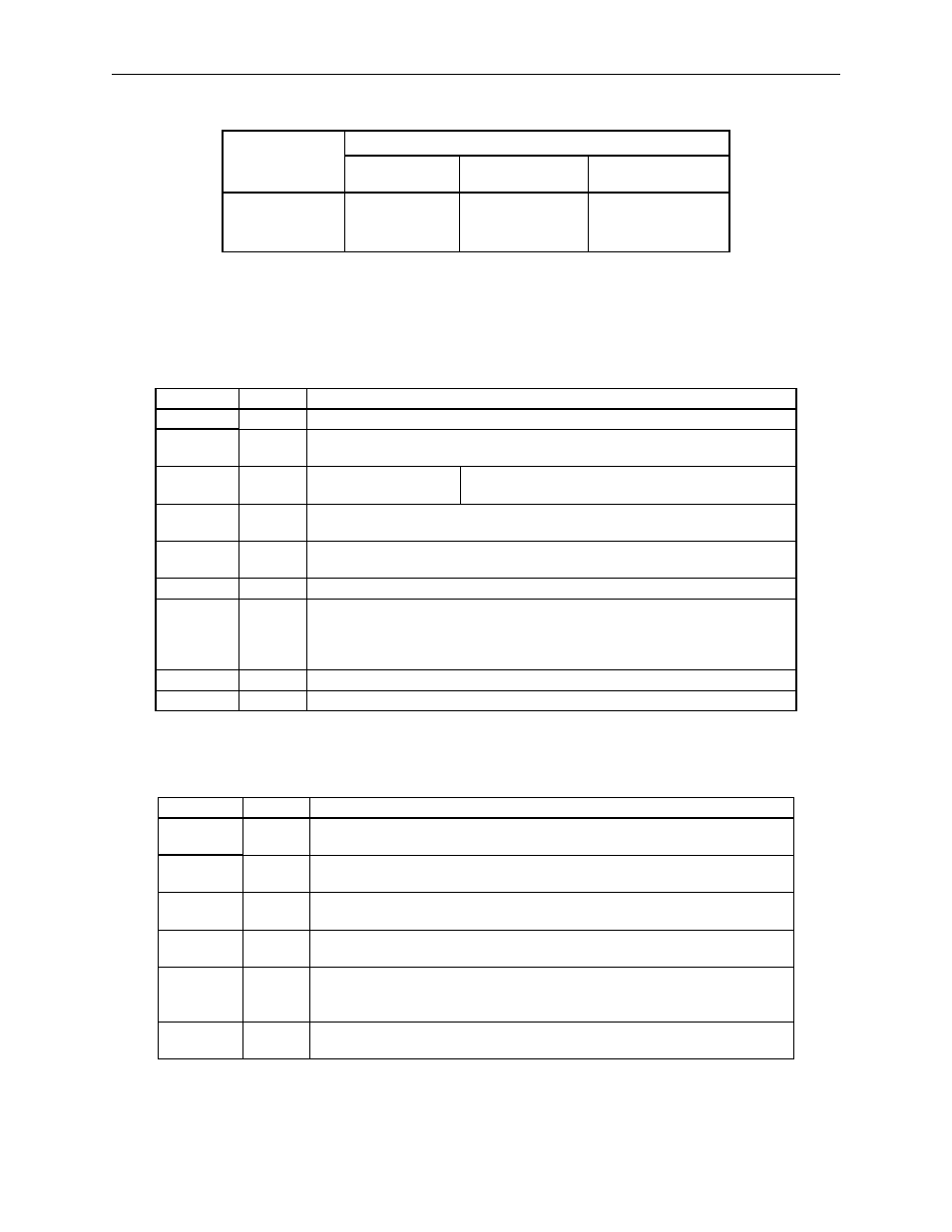
Table 3.4: CN4 Specifications (Sigma II Indexer)
Note: Yaskawa P/N DP9420007 includes 3M connector and case.
3.1.3 I/O Signal Names and Functions
The following section describes servo amplifier I/O signal names and functions.
Note 1. Pin numbers in parenthesis () indicate signal grounds.
Specifications for
Servo Amplifier
Receptacle
Applicable Mating Connector
Connector
Case
Manufacturer
10236–52A25L or
Equivalent 36–pin
Right Angle
Receptacle
10136–3000VE
10336–52A0–008
Sumitomo 3M Co.
Table 3.5: CN1 Input Signals (Servo Amplifier)
Signal Name Pin No.
Function
/S-ON
40
Servo ON: Turns ON the servomotor when the gate block in the inverter is released.
/SEL5
41
Mode 0: Program select input 5.
Mode 1: No effect.
P-OT
N-OT
42
43
Forward run prohibit
Reverse run prohibit
Overtravel prohibited: Stops Servo motor when movable
part travels beyond the allowable range of motion
/DEC
44
Zero point return deceleration limit switch:
Deceleration LS used when the motor returns to the zero point during homing.
/SEL6
45
Mode 0: Program select input 6.
Mode 1: No effect.
/RGRT
46
Registration latch signal: used for external positioning.
+24VIN
47
Control power supply input for sequence signals: User must provide the +24-V power
supply.
Minimum operating voltage: 11V
Maximum operating voltage: 25V
BAT (+)
21
Connecting pin for the absolute encoder backup battery
BAT (-)
22
Connect to either CN8 or CN1-21,22.
Table 3.6: CN1 Output Signals (Servo Amplifier)
Signal Name Pin No.
Function
ALM+
ALM-
31
32
Servo alarm: Turns OFF when an alarm is detected.
/WARN+
/WARN-
25
26
Servo Warning: ON when an error or warning is detected.
/BK+
/BK-
27
28
Brake interlock: Output that controls the brake.
The brake is released when this signal is ON.
/S-RDY+
/S-RDY-
29
30
Servo ready. ON if there is no servo alarm when
the control/main circuit power supply is turned ON.
ALO1
ALO2
ALO3
37
38
39 (1)
Alarm code output: Outputs 3-bit alarm codes
Open-collector: 30 V and 20 mA rating maximum
FG
Shell
Connected to frame ground if the shield wire of the
I/O signal cable is connected to the connector shell.