SMA SC 500CP XT User Manual
Page 97

10.3.3.6 Reactive Power Setpoint via Standard Signal: VArCnstNomAnIn Mode
The reactive power setpoint is set at the input terminals for the setpoints via an analog signal. This is usually
implemented by a ripple control signal. The analog value is converted into a reactive power setpoint. The electrical
current strength of the connected signal determines the setpoint. The analog measured values must be between
4 mA and 19 mA. If the analog signal is less than 2 mA, an error message will be displayed in the instantaneous value
Q‑VArModFailStt.
Signal
Power limit
Description
< 2 mA
Last valid mean value or 0 kVAr after
restart
Signal is in the invalid range.
2 mA to 4 mA
Qmax / underexcited
The maximum amount of negatively excited reactive
power is fed in.
4 mA
Qmax / underexcited
Start point of the characteristic curve
The maximum amount of negatively excited reactive
power is fed in.
11.5 mA
0 kVAr
Zero-crossing of the characteristic curve
No reactive power is fed in.
> 19 mA
Qmax / overexcited
End point of the characteristic curve
The maximum amount of positively excited reactive
power is fed in.
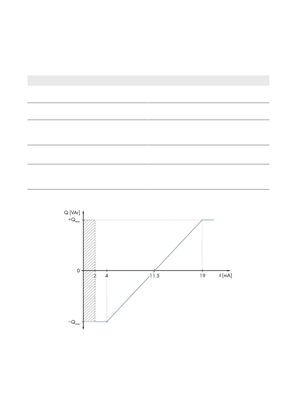
The analog value is converted to a setpoint for power limitation. Here, the parameter Qmax forms the end point of the
linear characteristic curve.
Figure 23: Limitation of the reactive power to the parameter Qmax
10.3.3.7 Reactive Power Setpoint via Displacement Power Factor cos φ: PFCnst Mode
The reactive power setpoint is set via the parameters PF‑PF and PF‑PFExt. The parameter PF‑PF indicates the
displacement power factor cos φ and the parameter PF‑PFExt indicates the degree of overexcitation or
underexcitation.
10 Function Description
SMA Solar Technology AG
User Manual
97
SCCPXT-BA-E4-en-54
- SC 630CP XT SC 720CP XT SC 760CP XT SC 800CP XT SC 850CP XT SC 900CP XT SC 500CP XT Maintenance Manual SC 630CP XT Maintenance Manual SC 720CP XT Maintenance Manual SC 760CP XT Maintenance Manual SC 800CP XT Maintenance Manual SC 850CP XT Maintenance Manual SC 900CP XT Maintenance Manual SC 1000CP XT SC 1000CP XT Maintenance Manual
