Machining variants – HEIDENHAIN TNC 640 (34059x-05) Cycle programming User Manual
Page 291

CONTOUR TURNING INTERPOLATION (Cycle 292, DIN/ISO: G292,
software option 96)
11.6
11
TNC 640 | User's Manual Cycle Programming | 1/2015
291
Machining variants
Before using Cycle 292, you first need to define the desired turning
contour in a subprogram and refer to this contour with Cycle 14 or
SEL CONTOUR. Describe the turning contour on the cross section
of a rotationally symmetrical body. Depending on the tool axis, use
the following coordinates to define the turning contour:
Tool axis used
Axial coordinate
Radial coordinate
Z
Z
X
X
X
Y
Y
Y
Z
Example:
If you are using the tool axis Z, program the turning
contour in the axial direction in Z and the radius of the contour in X.
You can use this cycle for inside and outside machining. The
following information illustrates some of the notes given in the
"Please note while programming" section. You can also find a
programming example in "Example: Interpolation Turning Cycle
292", page 313
Inside machining
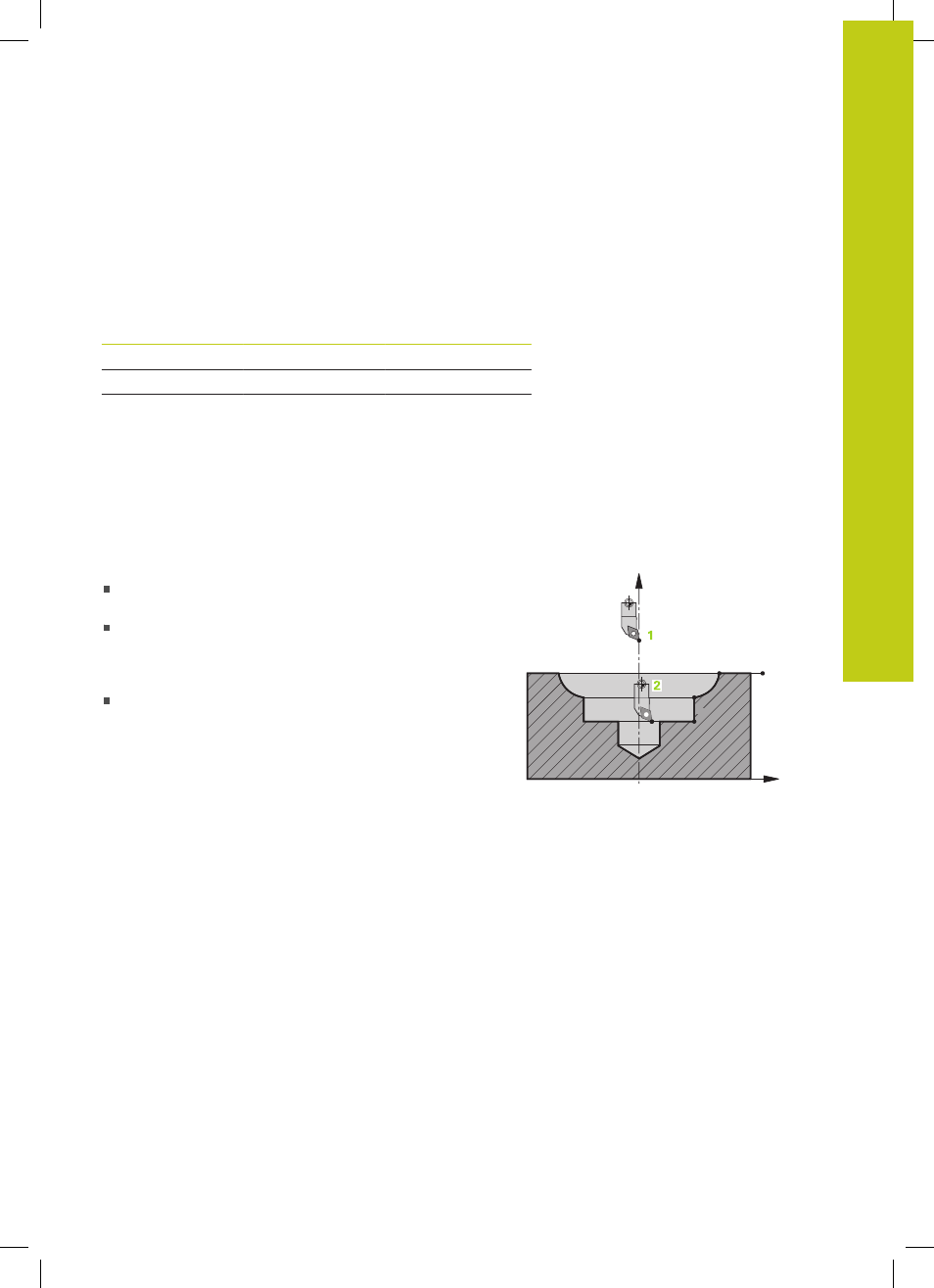
The center of rotation is the position of the tool in the
working plane at the time the cycle is called
1
After the cycle is started, neither the indexable
insert nor the spindle center must be moved into
the center of rotation!
Keep this in mind when
describing the contour!
2
The described contour is not automatically extended
by a set-up clearance. An extension of the contour
must be programmed in the subprogram. At the
beginning of the machining operation, the TNC
positions the tool at rapid traverse in the tool axis
direction to the contour starting point!
Make sure
that there is no material at the contour starting
point!
When programming an inside contour, please also
remember:
–
Program either monotonically increasing radial and
axial coordinates, e.g. 1-5
–
Or program monotonically decreasing radial and
axial coordinates, e.g. 5-1
–
Program inside contours with a radius greater than
the tool radius.
1
3
4
5
2
Z
X
