3 pulse inhibit input function (inhp), 4 electronic gear ratio, Pulse inhibit input function (inhibit) -4 – Delta Electronics AC Servo Drive ASDA-B User Manual
Page 119: 4 electronic gear ratio -4
Chapter 6 Control Modes of Operation|ASDA-B Series
6-4
Revision February 2008, Doc. Name: 2006PDD23000009
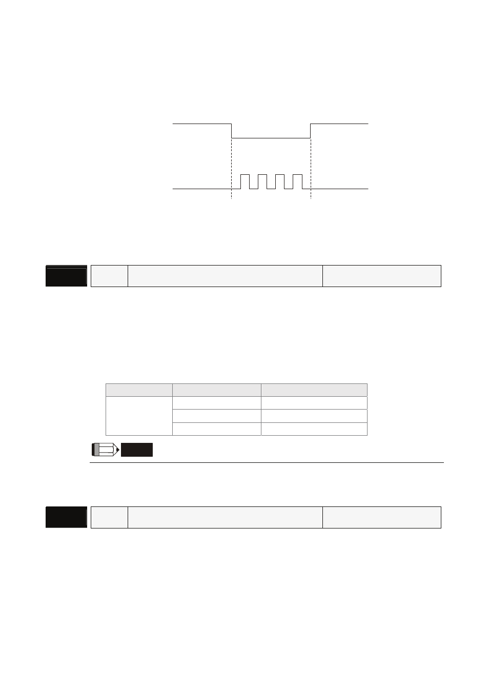
6.2.3 Pulse Inhibit Input Function (INHP)
INHP is activated via digital inputs (Please refer to parameter P2-10 ~ P2-15 and DI INHP(07) in Table
7.A).When the drive is in position mode, if INHP is activated, the external pulse input command is not
valid and the motor will stop.
Pulse
command
INHP
ON
OFF
ON
6.2.4 Electronic Gear Ratio
Relevant parameters:
P1 - 15▲
GR4
Electronic Gear Ratio (2nd Numerator) (N2)
Communication Addr.: 010FH
Default: 1
Related Section:
Applicable Control Mode: P
Section 6.2.4, P1-44, P1-45
Unit: pulse
DI GNUM0(11) in Table 7.A
Range: 1 ~ 32767
Settings:
The electronic gear numerator value can be set via external DI signal (refer to Table 7.A).
DI Name
DI Status
Selected Electronic Gear
Not select (Note 1)
P1-44, P1-45
0 P1-44,
P1-45
GNUM0
1 P1-44,
P1-45
NOTE
1) DI signal can be selected by parameter P2-10 to P2-15 and Table 7.A. If uses only need to
use one group of electronic gear, it allows users not to select GNUM0.
P1 - 44▲
GR1
Electronic Gear Ratio (1st Numerator) (N1)
Communication Addr.: 012CH
Default: 1
Related Section:
Applicable Control Mode: P
Section 6.2.4, P1-15, P1-45
Unit: pulse
DI GNUM0(11) in Table 7.A
Range: 1 ~ 32767
Settings:
The electronic gear numerator value can be set via external DI signal (refer to Table 7.A).