7 switch minor alarms 1, 1 programming steps – Comtech EF Data RCS20 User Manual
Page 92
RCS20 M:N Redundancy Switch
Revision 15
User Interfaces
MN-RCS20 and CD-RCS20
4–58
4.3.3.7 SWITCH MINOR ALARMS 1
These screens display the RCS20 minor alarms, and allow the user to mask these alarms. When an
alarm is masked, the error will not be reported on the front panel MINOR ALARM Lamp or on the ALARM
connector at the rear of the RCU20. The POWER SUPPLY 1 PRESENT Alarm indicates that slide-in
Power Supply Module 1 is fully seated in the RCU20. The POWER SUPPLY 1 VOLTAGE Alarm indicates
a voltage problem with slide-in Power Supply Module 1. The remaining two alarms indicate the same
conditions for slide-in Power Supply Module 2.
CAUTION
Masking alarms may cause undesirable modem performance
4.3.3.7.1 Programming steps:
1. Press or to move the flashing cursor the channel to be programmed
2. Press
indicates an alarm is not masked.
3. Press
4. Press
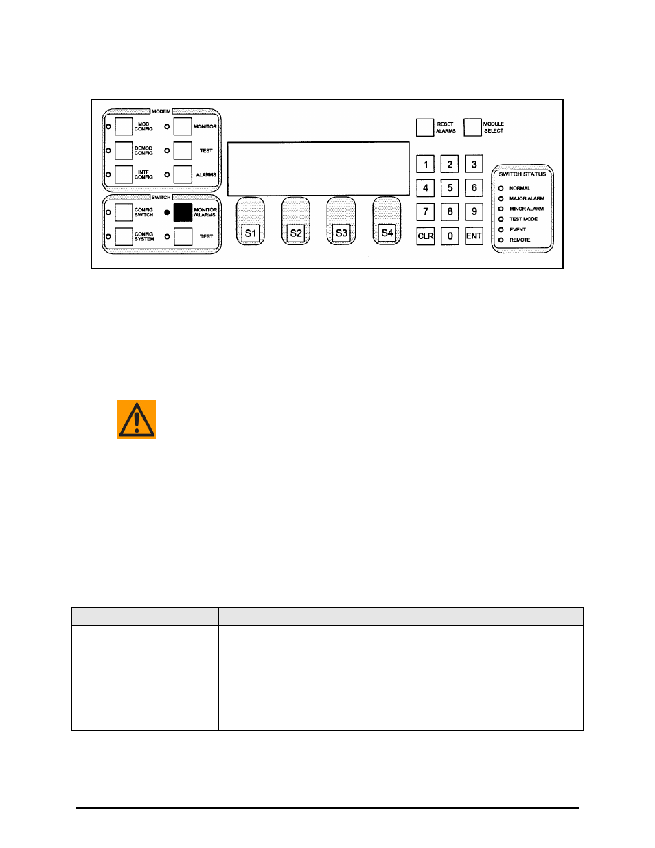
Key
Label
Function
S1
Press to move the blinking cursor up through the list of faults.
S2
Press to move the blinking cursor down through the list of faults.
S3
TOG MODE Used to toggle between YES (masked) and NO (not masked).
S4
NEXT
Press to cycle to the next screen.
Numeric Keypad ---
Press
Press
SWITCH MINOR ALARMS
MASK
POWER SUPPLY 1 PRESENT : FAIL YES
POWER SUPPLY 1 VOLTAGE : FAIL YES
POWER SUPPLY 2 PRESENT : PASS NO
POWER SUPPLY 2 VOLTAGE : PASS NO
TOG MODE NEXT