2 modem addresses, 1 programming steps – Comtech EF Data RCS20 User Manual
Page 42
RCS20 M:N Redundancy Switch
Revision 15
User Interfaces
MN-RCS20 and CD-RCS20
4–8
2. Press
3. Press
4. Press
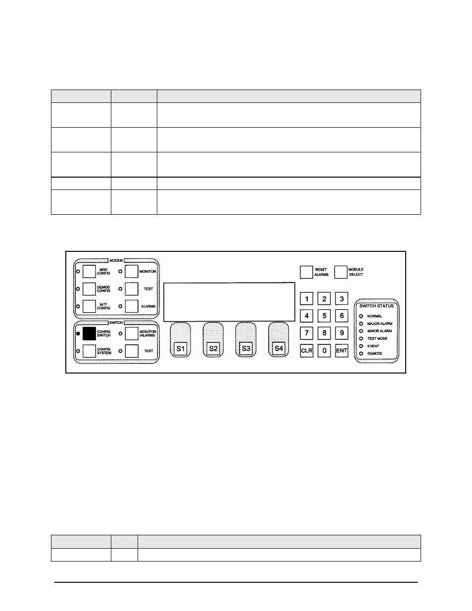
Key
Label
Function
S1
Press to move the blinking cursor to the left. Used to select the channel
connection.
S2
Press to move the blinking cursor to the left. Used to select the channel
connection.
S3
TOG
MODE
Used to toggle through the choices above. Multiple connections may be entered.
S4
NEXT
Press to cycle to the next screen.
Numeric Keypad ---
Press
Press
4.3.1.2 MODEM ADDRESSES
This screen allows the user to program the remote addresses of each modem connected to the
redundancy system. All addresses must be in the range of 32 to 255 decimal. All entries on this screen
are in decimal. Multiple addresses may be programmed.
4.3.1.2.1 Programming steps:
1. Press or to move the blinking cursor to the channel to be programmed.
2. Use the numeric keypad to enter the address for the channel at the cursor.
3. Enter an address for each modem connected to the redundancy system at the blinking cursor.
Addresses for channels that do not have a modem connected will be ignored.
4. Press
5. Press
Key
Label
Function
S1
Press to move the blinking cursor to the left. Used to select the modem (labeled Modems
MODEM ADDRESSES USE KEYPAD
B2 B1
1 2 3 4 5 6 7 8 9 0
101 102 103 104 105 106 107 108 109 110
<--- ---> NEXT