5 ifs20 intermediate frequency switch units, 1 ifs20 70/140 mhz unit, 1 j1 | up aux – Comtech EF Data RCS20 User Manual
Page 125: 2 j2 | up1, 3 j3 | up2, 4 j4 | up3, 5 j5 | up4, 6 j6 | up5
RCS20 M:N Redundancy Switch
Revision 15
Electrical Interfaces
MN-RCS20 and CD-RCS20
5–25
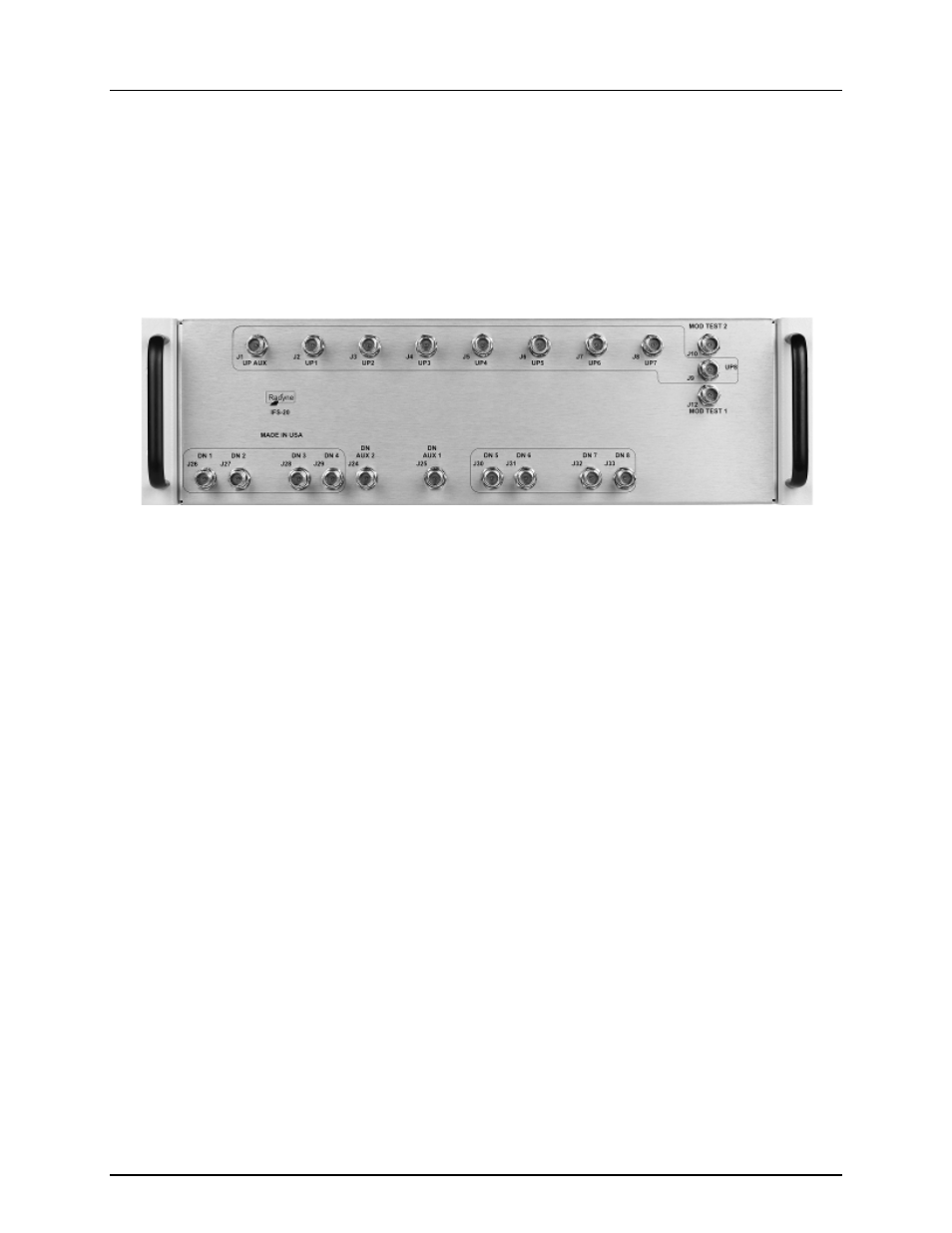
5.5 IFS20 Intermediate Frequency Switch Units
5.5.1 IFS20 70/140 MHz Unit
5.5.1.1 IFS20 70/140 MHz Unit Connectors – Front Panel
The IFS20 has connections to both the front and back panels (Figures 5-15 and 5-16). Unless otherwise
indicated, all IF connectors are 75 Ohm Female BNC connectors.
Figure 5-15 IFS20 Front Panel Connectors
5.5.1.1.1 J1 | UP AUX
The J1 | UP AUX External Output port is used for connecting satellite transmission channel 9 to an up
converter or combiner in a 1:9 system.
5.5.1.1.2 J2 | UP1
The J2 | UP1 port is used for connecting satellite transmission channel 1 to an up converter or combiner.
5.5.1.1.3 J3 | UP2
The J4 | UP2 port is used for connecting satellite transmission channel 2 to an up converter or combiner.
5.5.1.1.4 J4 | UP3
The J4 | UP3 port is used for connecting satellite transmission channel 3 to an up converter or combiner.
5.5.1.1.5 J5 | UP4
The J5 | UP4 port is used for connecting satellite transmission channel 4 to an up converter or combiner.
5.5.1.1.6 J6 | UP5
The J6 | UP5 port is used for connecting satellite transmission channel 5 to an up converter or combiner.