3 monitor/alarms menu tree, 2 mod / demod fault monitor – Comtech EF Data RCS20 User Manual
Page 88
RCS20 M:N Redundancy Switch
Revision 15
User Interfaces
MN-RCS20 and CD-RCS20
4–54
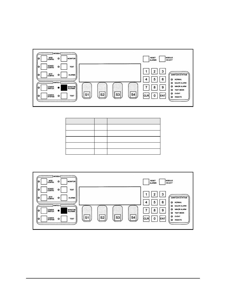
4.3.3 MONITOR/ALARMS Menu Tree
4.3.3.1 EXPANSION SLOT MONITOR
This screen displays the contents of the expansion slots at the rear of the RCU20.
Key
Label
Function
S1
---
N/A
S2
---
N/A
S3
---
N/A
S4
NEXT Press to cycle to the next screen.
Numeric Keypad ---
N/A
4.3.3.2 MOD / DEMOD FAULT MONITOR
This screen displays the fault status of the all prime and backup channel modulators and demodulators.
The fault status each modem is reported to the DDS20 through two open collector connections in the 68-
pin cable between each modem and the DDS20. The logic state of these status lines is then reported to
the RCU20 through the 15-pin high-density serial cable between the DDS20 and the RCU20. The
following letter codes may be used:
EXPANSION SLOT MONITOR
SLOT 0: (EMPTY)
SLOT 1: USER INTERFACE
SLOT 2: BANK CONTROL:(IFS20A, DDS20)
SLOT 3: (EMPTY)
SLOT 4: (EMPTY)
SLOT 5: UNKNOWN TYPE NEXT
MOD / DEMOD FAULT MONITOR
BACKUP : B2 B1
MODEM : 1 2 3 4 5 6 7 8 9 0
CONNECT:md md md md md md md md md md
FAULT :FF ?? FF ?? FF FF ?? ?? FF FF
NEXT