A.1.2 protocol wrapper – Comtech EF Data RCS20 User Manual
Page 144

RCS20 M:N Redundancy Switch
Revision 15
Remote Operations
MN-RCS20 and CD-RCS20
A–2
A.1.2 Protocol Wrapper
The Radyne COMMSPEC is byte-oriented, with the Least Significant Bit (LSB) issued first. Each data
byte is conveyed as mark/space information with one mark comprising the stop data. When the last byte
of data is transmitted, a hold comprises one steady mark (the last stop bit). To begin or resume data
transfer, a space (00h) substitutes this mark. This handling scheme is controlled by the hardware and is
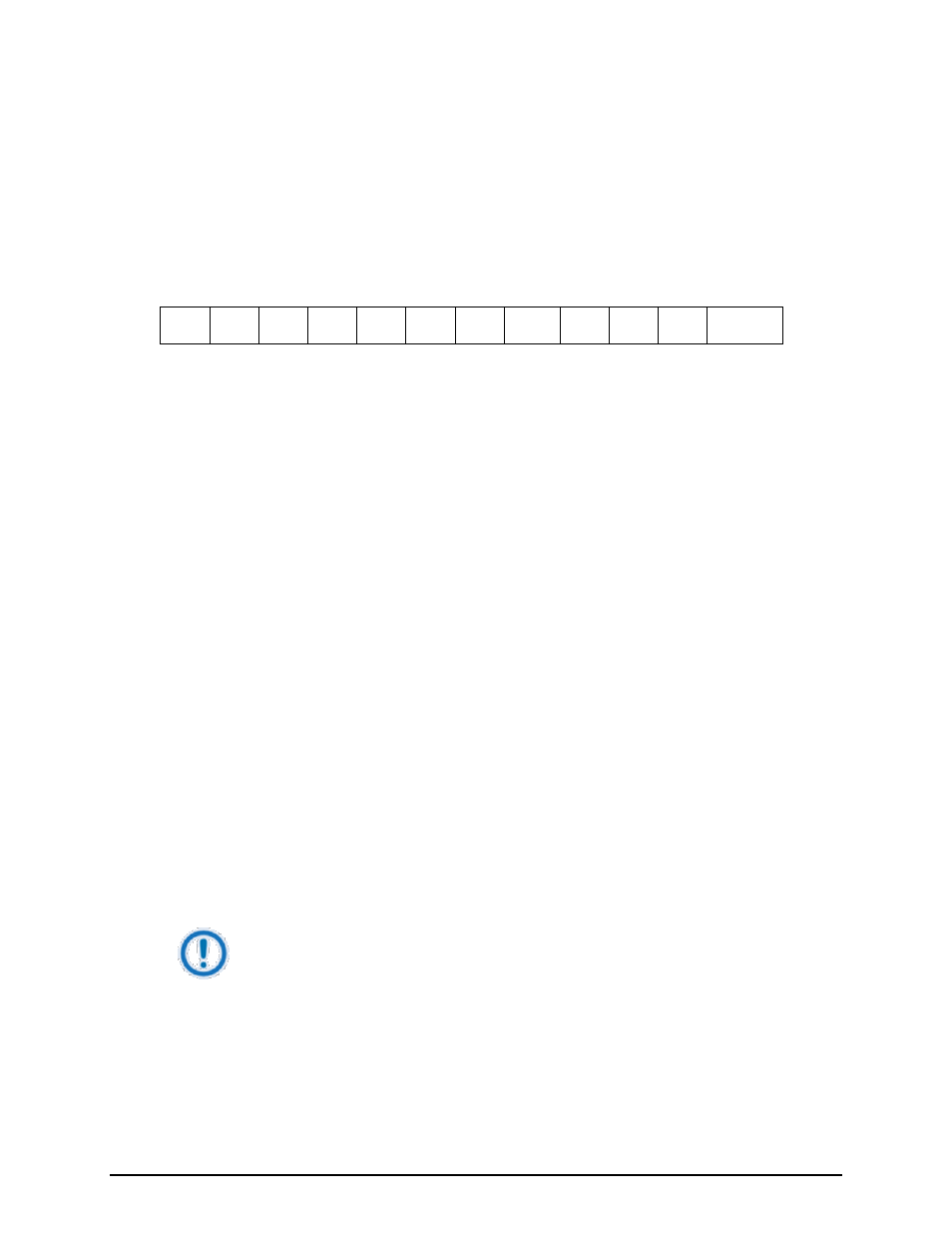
transparent to the user. A pictorial representation of the data and its surrounding overhead may be shown
as follows:
S1
S2
B
0
B
1
B
2
B
3
B
4
B
5
B
6
B
7
S1
S2, etc
The stop bits, S1 and S2 are each a mark. Data flow remains in a hold mode until S2 is replaced by a
space. If S2 is followed by a space, it is considered a start bit for the data byte and not part of the actual
data (B
0
- B
7
).
The above byte-oriented protocol is standard for UART based serial communication ports such as
Workstation or Personal Computer (PC) COM ports. COM ports should be configured for 8 data bits, no
parity, and one stop bit. For example, for 9600-baud operation, COM ports should be configured as 9600,
8, N, 1.
The COMMSPEC developed for use with the Radyne Link Level Protocol (RLLP) organizes the actual
monitor and control data within a shell, or ‘protocol wrapper’, that surrounds the data. The format and
structure of the COMMSPEC message exchanges are described herein. Decimal numbers have no suffix;
hexadecimal numbers end with a lower case h suffix and binary values have a lower case b suffix. Thus,
22 = 16h = 00010110b. The principal elements of a data frame, in order of occurrence, are summarized
as follows:
message. The
TBD, (2 bytes).
IMPORTANT
All nodes on a given control bus have a unique address that must be defined.
the message is sent, (1 byte).
