3 front panel screens, 1 config switch menu tree, 1 programming steps – Comtech EF Data RCS20 User Manual
Page 41
RCS20 M:N Redundancy Switch
Revision 15
User Interfaces
MN-RCS20 and CD-RCS20
4–7
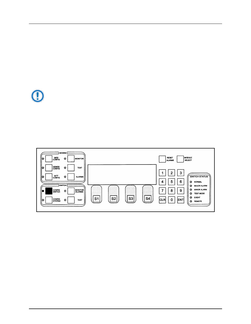
4.3 Front Panel Screens
There are four menu trees used to control the RCS20:
•
CONFIG SWITCH
•
CONFIG SYSTEM
•
MONITOR/ALARMS
•
TEST
These menu trees and their functions are discussed in the subsections that follow.
NOTE
The screens as depicted in the subsections that follow are representations. Your screens
may vary slightly.
4.3.1 CONFIG SWITCH Menu Tree
4.3.1.1 MODEM CHANNEL CONNECTIONS
This screen allows the user to assign connections to the channels. The RCS20 must be programmed with
satellite channel numbers used for redundancy protection. Channel 0 is the dedicated backup, and
Channel 9 may either be prime or backup. Channels 1 to 8 are dedicated backups. These connections
may be any of the following:
•
m - modulator
•
d - demodulator
•
md - modulator/demodulator
•
none - No Connection
4.3.1.1.1 Programming steps:
1. Press or to move the blinking cursor to the channel to be programmed
MODEM CHANNEL CONNECTIONS
BACKUP : B2 B1
MODEM : 1 2 3 4 5 6 7 8 9 0
CONNECT:md md md md md md md md md md
<--- ---> TOG MODE