4 j1 | modem remote, 5 j2 | ifs20, 6 j3 | dds20 – Comtech EF Data RCS20 User Manual
Page 108
RCS20 M:N Redundancy Switch
Revision 15
Electrical Interfaces
MN-RCS20 and CD-RCS20
5–8
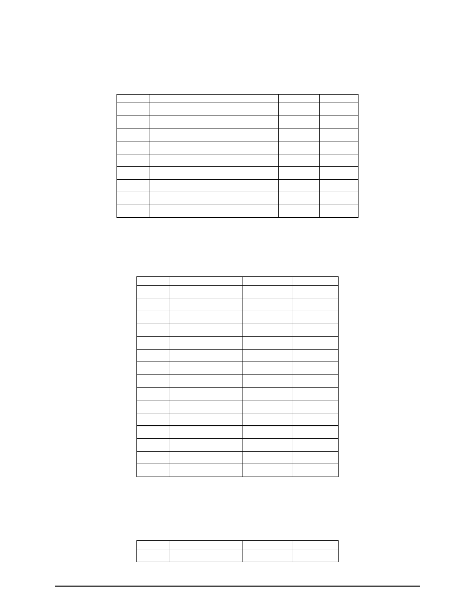
5.2.3.2.4 J1 | MODEM REMOTE
The J1 | MODEM REMOTE EIA-485 Control port is a 9-Pin Type D Female Connector. It is used as an
RS485 bus to interface to the modems remote ports
Pin No.
Signal Name
Signal
Direction
1
EIA-485/HDLC Receive Data B (+)
TxD-B
Input
2
HDLC Receive Clock A (-)
TCLK-A
Input
3
HDLC Receive Clock B (+)
TCLK-B
Input
4
HDLC Transmit Clock A (-)
RCLK-A
Output
5
Signal Common
COMMON ---
6
EIA-485/HDLC Receive Data A (-)
TxD-A
Output
7
HDLC Transmit Clock B (+)
RCLK-B
Output
8
EIA-485/HDLC Transmit Data B (+) RxD-B
Output
9
EIA-485/HDLC Transmit Data A (-)
RxD-A
Output
5.2.3.2.5 J2 | IFS20
The J2 | IFS20 Control and Power port is a 15-Pin High-Density Type HD Female Connector.
Pin No.
Signal Name
Signal
Direction
1
Serial Control Clock IFS_LCLK
Output
2
No Connection
N/C
---
3
No Connection
N/C
---
4
Ground
GND
---
5
Ground
GND
---
6
Logic +5 Volts
VCC
Output
7
Relay +6 Volts
VCC_RELAY Output
8
No Connection
N/C
---
9
No Connection
N/C
---
10
Ground
GND
---
11
Relay +6 Volts
VCC_RELAY Output
12
Serial Control Data 1 IFS_LDAT1
Bidirectional
13
No Connection
N/C
---
14
No Connection
N/C
---
15
No Connection
N/C
---
5.2.3.2.6 J3 | DDS20
The J3 | DDS20 Control and Power port is a 15-Pin High-Density Type D Female Connector.
Pin No.
Signal Name
Signal
Direction
1
Serial Control Clock DDS_LCLK
Output