3 modem channel connection test, 1 programming steps – Comtech EF Data RCS20 User Manual
Page 43
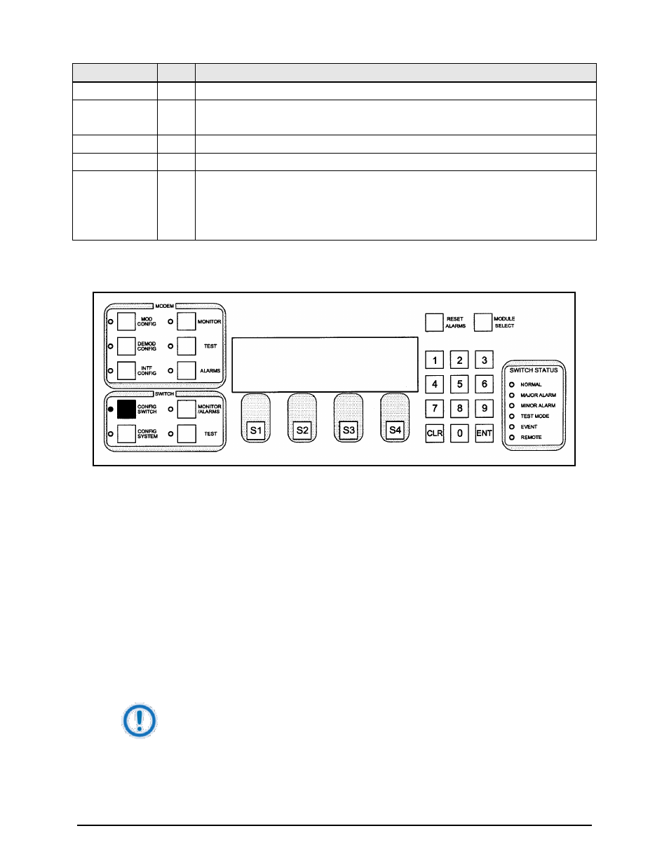
RCS20 M:N Redundancy Switch
Revision 15
User Interfaces
MN-RCS20 and CD-RCS20
4–9
Key
Label
Function
1 through 0) to which the address is to be changed.
S2
Press to move the blinking cursor to the right. Used to select the modem (labeled
Modems 1 through 0) to which the address is to be changed.
S3
---
N/A
S4
NEXT Press to cycle to the next screen.
Numeric Keypad ---
Enter an address for each modem connected to the redundancy system at the blinking
cursor. Addresses for channels that do not have a modem connected will be ignored.
Press
Press
4.3.1.3 MODEM CHANNEL CONNECTION TEST
This screen allows the user to test communication channels between the RCS20 and all modems
connected to the system. The ** indicates communication is in progress, and will move between all
configured channels before the test is complete.
4.3.1.3.1 Programming steps:
1. Press
A ‘Y’ in the ACTIVE Row indicates normal communication, and an ‘N’ indicates communication failure
between the RCS20 and the modems. The MODEM Row lists the communication channels for each
modem. For example, an ‘N’ in the ACTIVE Row under Modem 4 indicates a problem with the modem
connected to Channel 4. Possible problems could be a bad connection to the Modem 4 Remote Port, or
an incorrect address for Modem 4, either at the modem or at the RCS20.
IMPORTANT
This test is performed approximately every 30 seconds by the RCS20, and the ** may
appear without pressing
MODEM CHANNEL CONNECTION TEST
BACKUP : B2 B1
MODEM : 1 2 3 4 5 6 7 8 9 0
CONNECT:md md md md md md md md md md
ACTIVE :YY YY YY ** YY YY NN NN NN NN