1 j1 | ext a in (external input a) – Comtech EF Data RCS20 User Manual
Page 104
RCS20 M:N Redundancy Switch
Revision 15
Electrical Interfaces
MN-RCS20 and CD-RCS20
5–4
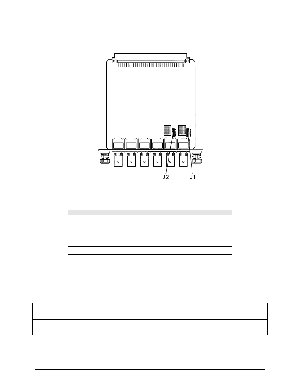
The Reference Distribution Module must be configured with two jumpers to select the termination
impedance. The jumpers, J1 and J2, are shown in Figure 5-4.
Figure 5-4 Reference Distribution Module Jumper Settings
Set the jumpers according to the following table to get the required termination impedance:
Termination Impedance (Ohms)
J1
J2
50Ω
Pins 1 and 2 Shorted
Pins 3 and 4 Open
Pins 1 and 2 Shorted
Pins 3 and 4 Open
75Ω
Pins 1 and 2 Open
Pins 3 and 4 Shorted
Pins 1 and 2 Open
Pins 3 and 4 Shorted
510Ω
All Pins Open
All Pins Open
The RDM also contains an internal reference in two options – high-stability or normal. These options and
the specifications for the module connectors follow.
5.2.3.1.1 J1 | EXT A IN (External Input A)
Impedance
50, 75, 510 Ohms (Jumper-Selectable)
Frequency
1.25, 2.5, 5.0 and 10.0 MHz
Input Level
Specification
High-Level 2 to 5 Volt
Low-Level 0 to 0.8 Volts