2 j2 | ext b in (external input b), 3 internal reference (option 1), 4 internal reference (option 2) – Comtech EF Data RCS20 User Manual
Page 105: 6 microprocessor interface, 7 board outline
RCS20 M:N Redundancy Switch
Revision 15
Electrical Interfaces
MN-RCS20 and CD-RCS20
5–5
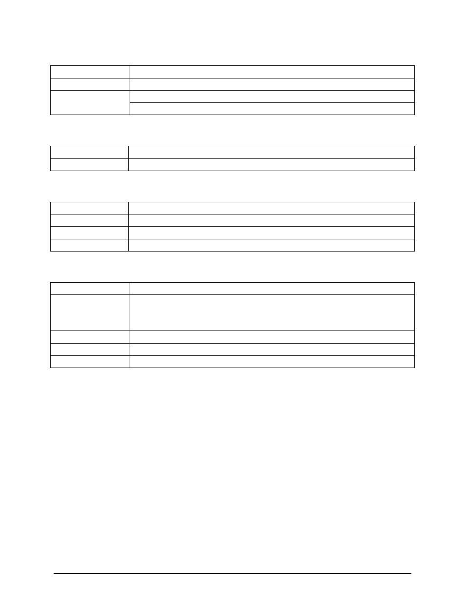
5.2.3.1.2 J2 | EXT B IN (External Input B)
Impedance
50, 75, 510 Ohms (Jumper-Selectable)
Frequency
1.25, 2.5, 5.0 and 10.0 MHz
Input Level
Specification
High-Level 2 to 5 Volt
Low-Level 0 to 0.8 Volts
5.2.3.1.3 Internal Reference (Option 1)
Stability
1 x 10
-5
Output Frequency
1.25, 2.5, 5.0 and 10.0 MHz (Program-Selectable to Match External Input)
5.2.3.1.4 Internal Reference (Option 2)
Stability
1 x 10
-8
Aging (day)
1 x 10
-8
Aging (year)
1 x 10
-8
Output Frequency
1.25, 2.5, 5.0 and 10.0 MHz (Program-Selectable to Match External Input)
5.2.3.1.5 Reference Outputs (J3 | OUT 1, J4 | OUT 2, J5 | OUT 3, J6 | OUT 4)
Output Level
TTL
Output Current Drive
48 mA Maximum – Sufficient to drive:
(5) DMD20s, DM240s, or DMD2401s
(3) DMD2400s
Output Frequency
1.25, 2.5, 5.0 and 10.0 MHz (Program-Selectable to Match External Input)
Output Impedance
50 Ohms
Short Circuit Resistant
5.2.3.1.6 Microprocessor Interface
•
External 1/External 2/Internal Reference Select
•
External Input Activity Detectors
•
Internal Reference Activity Detector
5.2.3.1.7 Board Outline
•
RCS20 Option Card Slot/DIN Connector