2 ifs20l l-band unit, 1 ifs20l l-band unit connectors – front panel, 1 j13 | modem 1 – Comtech EF Data RCS20 User Manual
Page 130: 2 j14 | modem 2, 3 j15 | modem 3, 4 j16 | modem 4, 6 j18 | modem 5
RCS20 M:N Redundancy Switch
Revision 15
Electrical Interfaces
MN-RCS20 and CD-RCS20
5–30
5.5.2 IFS20L L-Band Unit
The IFS20L has connections to both the front and back panels (shown in Figures 5-17 and 5-18). Unless
otherwise indicated, all L-Band connectors are 50 Ohm Female SMA connectors.
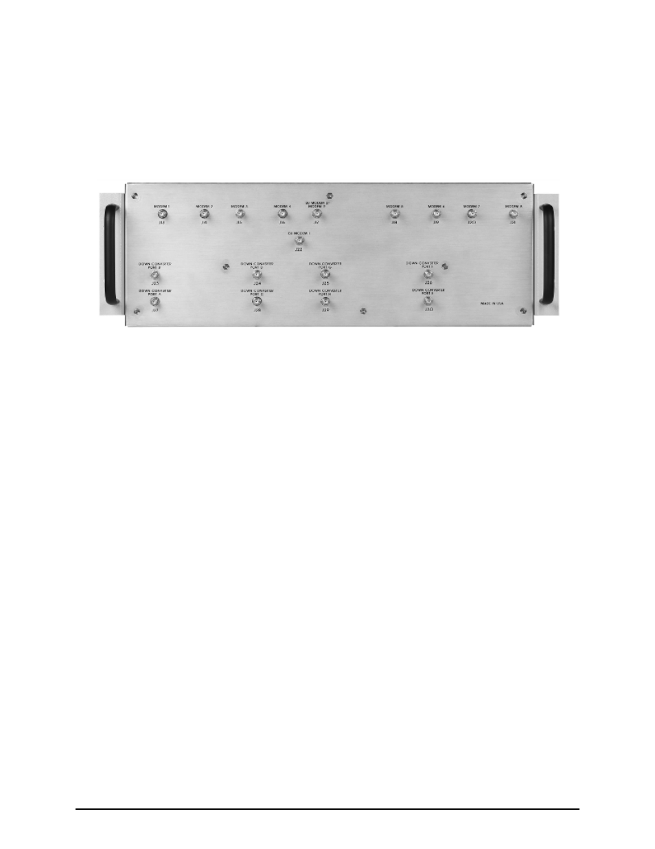
5.5.2.1 IFS20L L-Band Unit Connectors – Front Panel
Figure 5-17 IFS20L Front Panel Connectors
5.5.2.1.1 J13 | MODEM 1
The J13 | MODEM 1 port is used connecting to the prime modem 1 L-Band transmit port.
5.5.2.1.2 J14 | MODEM 2
The J14 | MODEM 2 port is used for connecting to the prime modem 2 L-Band transmit port.
5.5.2.1.3 J15 | MODEM 3
The J15 | MODEM 3 port is used for connecting to the prime modem 3 L-Band transmit port.
5.5.2.1.4 J16 | MODEM 4
The J16 | MODEM 4 port is used for connecting to the prime modem 4 L-Band transmit port.
5.5.2.1.5 J17 | BU MODEM 2 | MODEM 9
The J17 | BU MODEM 2 | MODEM 9 port is used for connecting to backup modem 2 L-Band transmit port
in a 2:N system or to a prime modem 9 L-Band transmit port in a 1:9 system.
5.5.2.1.6 J18 | MODEM 5
The J18 | MODEM 5 port is used for connecting to the prime modem 5 L-Band transmit port.