4 modem 9 / backup 2 configuration, 1 programming steps – Comtech EF Data RCS20 User Manual
Page 44
RCS20 M:N Redundancy Switch
Revision 15
User Interfaces
MN-RCS20 and CD-RCS20
4–10
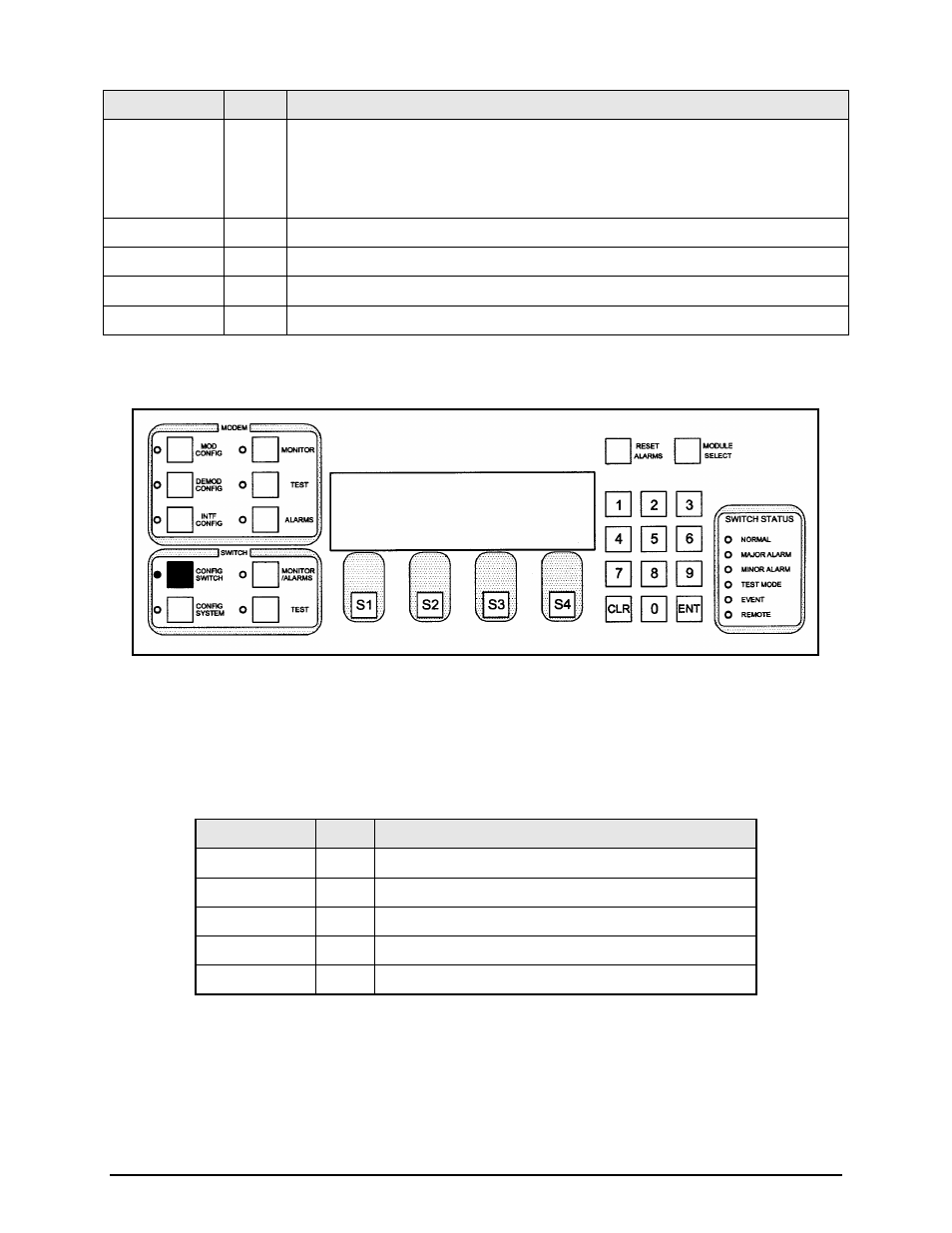
Key
Label
Function
S1
START
Press to begin the test. As each modem is being tested, the screen will indicate
astericks (**) at that location in the ACTIVE row. As the astericks move across the
screen, a ‘Y’ or N will appear indicating if the modulator and/or demodulator has a valid
connection.
S2
---
N/A
S3
---
N/A
S4
NEXT
Press to cycle to the next screen.
Numeric Keypad ---
N/A
4.3.1.4 MODEM 9 / BACKUP 2 CONFIGURATION
This screen allows the user to select the mode operation for Channel 9. The Channel 9 Modem can
operate as a prime or backup.
4.3.1.4.1 Programming steps:
1. Press
Key
Label
Function
S1
MODE Press to go the MODEM 9 / BACKUP 2 MODE Subscreen.
S2
---
N/A
S3
---
N/A
S4
NEXT Press to cycle to the next screen.
Numeric Keypad ---
N/A
MODEM 9 /
MODEM9 MODE : BACKUP
MODE NEXT
- CDD-880 (124 pages)
- CDM-800 (130 pages)
- ODMR-840 (184 pages)
- CDM-750 (302 pages)
- CDM-840 (244 pages)
- SLM-5650A (420 pages)
- CTOG-250 (236 pages)
- CDM-700 (256 pages)
- CDM-760 (416 pages)
- CDM-710G (246 pages)
- CDM-600/600L (278 pages)
- CDMR-570L (512 pages)
- CDM-625 (684 pages)
- CDM-625A (756 pages)
- CDD-564A (240 pages)
- CDD-564L (254 pages)
- CLO-10 (134 pages)
- MCED-100 (96 pages)
- CDMR-570AL (618 pages)
- CDM-600 LDPC (2 pages)
- BUC Power Supply Ground Cable (2 pages)
- MPP70 Hardware Kit for CDM-570L (4 pages)
- MPP50 Hardware Kit for CDM-570L (4 pages)
- CDM-625 DC-AC Conversion (4 pages)
- CDM-625 DC-AC Conversion with IP Packet Processor (4 pages)
- DMDVR20 LBST Rev 1.1 (117 pages)
- DMD2050E (212 pages)
- DMD-2050 (342 pages)
- DMD1050 (188 pages)
- OM20 (220 pages)
- QAM256 (87 pages)
- DD240XR Rev Е (121 pages)
- MM200 ASI Field (5 pages)
- DM240-DVB (196 pages)
- MM200 (192 pages)
- CRS-150 (78 pages)
- CRS-280L (64 pages)
- CRS-170A (172 pages)
- CRS-180 (136 pages)
- SMS-301 (124 pages)
- CiM-25/8000 (186 pages)
- CiM-25 (26 pages)
- CRS-500 (218 pages)
- CRS-311 (196 pages)
- CIC-20 LVDS to HSSI (26 pages)