1 programming steps for setting up the link – Comtech EF Data RCS20 User Manual
Page 81
RCS20 M:N Redundancy Switch
Revision 15
User Interfaces
MN-RCS20 and CD-RCS20
4–47
4.3.2.21.1 Programming Steps for setting up the link:
1.
Establish a link from the prime channel to the far end modem using TX IF = RX IF and CnC
2.
Learn Prime Modem
3.
Test Prime Modem
4.
Set BU modem to IF LOOPBACK
5.
Verify no alarms
IMPORTANT
In Carrier and Carrier switching mode the RCS20 does NOT support Independent
Modulator and demodulator Switching as seen in Section 4.3.1.6 (Modem Switching
Style). Also, on the RCS20 you will want to set the Mod and Demod Fault Delay
(Sections 4.3.1.9.4 and 4.3.1.9.5) to 5 seconds minimum. You will also need to set the
Demod Acquisition Delay (Section 4.3.9.6) to a minimum of 30 seconds. This will
account for the time it may take for CnC to properly acquire.
Also note that the modems listed above must be configured to use the Base Band
Relays in CnC 1:1 SWITCH mode. This menu entry on the modems listed above can
be found under the Menu: INTERFACE -> GENERAL ->BB RELAYS {CnC 1:1
SWITCH}.
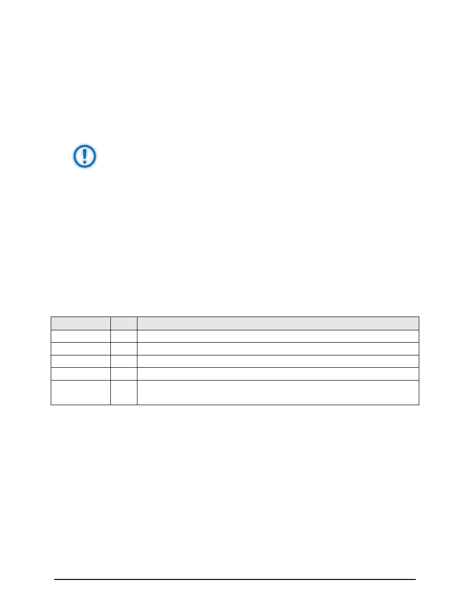
Key
Label
Function
S1
CNC
Press to change CnC Switching Mode.
S2
---
N/A
S3
---
N/A
S4
NEXT Press to cycle to next screen.
Numeric Keypad ---
Press
the BANK CONTROL CONFIGURATION Screen