5 switch status leds, 6 numeric keypad, 7 soft keys (s1 - s4) – Comtech EF Data RCS20 User Manual
Page 38
RCS20 M:N Redundancy Switch
Revision 15
User Interfaces
MN-RCS20 and CD-RCS20
4–4
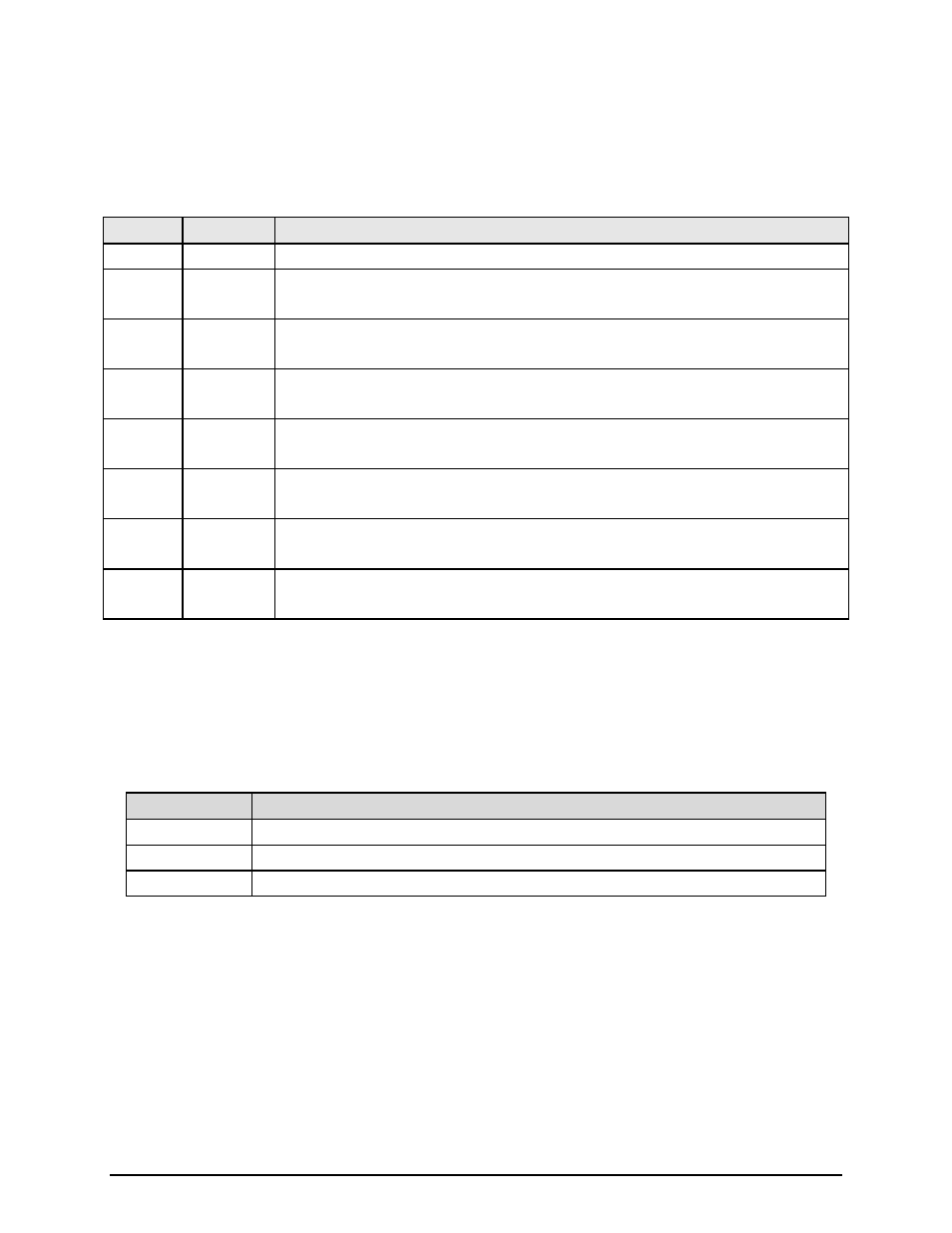
4.2.5 Switch Status LEDs
Refer to Table 4-2 for the description and colors of the Switch Status LEDs. 4.2.1.6 MODEM ALARMS.
Table 4-2. Switch Status LED Function
LED
Color
Description
Normal
Green
Indicates that the unit is currently under power.
Major
Alarm
Red
Indicates that at least one satellite channel did not receive Redundancy protection and is
off-line.
Minor
Alarm
Yellow
Indicates that a Redundancy warning exists and the RCS20 may not be providing
Redundancy protection.
Minor
Alarm
Flashing
Yellow
Indicates a prime modem configuration. The configuration change should be taught.
Test
Mode
Yellow
Indicates that the switch is performing one of the system tests.
Event
Yellow
Indicates that a condition of system event as occurred that the RCS20 has stored in
memory. The events may be viewed from the Front Panel or from the Terminal port.
Event
Flashing
Yellow
Indicates a prime modem is currently being backed-up.
Remote
Green
Indicates that the unit is set to respond from either the Terminal port or the Remote M&C
port
4.2.6 Numeric Keypad
This group of keys is used to perform various functions for the RCS20 and connected modems. Table 4-3
describes the function of these keys.
Table 4-3. Numeric Keypad Function
Key
Description
ENTER
Loads edited values into memory and advances to next screen in the menu tree.
CLEAR
Aborts loading values into memory and advances to the previous screen in the menu tree.
Numeric keys 0-9 Used to edit numeric parameters.
4.2.7 Soft Keys (S1 - S4)
This group of keys is used for various functions as described by the label shown above each key on the
bottom line of the LCD Display.