4 active minor alarms – Comtech EF Data RCS20 User Manual
Page 137
RCS20 M:N Redundancy Switch
Revision 15
Maintenance and Troubleshooting
MN-RCS20 and CD-RCS20
6–3
6.4 Active Minor Alarms
Minor Alarms mean a failure condition exists that does not immediately result in loss of service on one or
more primary satellite channels. However, a minor alarm may mean that there is a loss of redundancy
protection for one or more channels. The RCS20 shows a Minor Alarm by lighting the MINOR ALARM
LED on the front panel, and closing a relay on the rear panel ALARM connector. Conditions resulting in
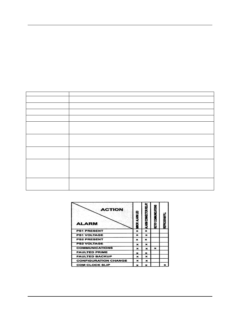
an RCS20 Minor Alarm are listed in Table 6-2 and a Minor Alarm matrix is shown in Figure 6-2. The alarm
matrix shows all possible alarm conditions and the actions taken by the RCS20 in response to the alarm.
Table 6-2. RCS20 Minor Alarms
Alarm
Description
PS 1 PRESENT
The slide in power supply module in position PS1 is missing or not fully-seated.
PS 1 VOLTAGE
The slide in power supply module in position PS1 is supplying the incorrect voltage.
PS 2 PRESENT
The slide in power supply module in position PS1 is missing or not fully seated.
PS 2 VOLTAGE
The slide in power supply module in position PS1 is supplying the incorrect voltage.
COMMUNICATIONS
One or more of the modems connected to the RCS20 have stopped responding to remote
communications from the switch.
FAULTED PRIME
One or more of the modems connected to the RCS20 that are designated as prime
channels have failed.
FAULTED BACKUP
One or more of the modems connected to the RCS20 that are designated as backup
channels have failed.
CONFIGURATION
CHANGE
One or more of the modems connected to the RCS20 that are designated as prime
channels have modem configurations that have changed while the RCS20 is in automatic
switch mode.
CDM CLOCK SLIP
One or more of the clock outputs on a Clock Distribution Module have lost lock with the
external reference.
Figure 6-2. Minor Alarm Matrix