Comtech EF Data RCS20 User Manual
Page 122
RCS20 M:N Redundancy Switch
Revision 15
Electrical Interfaces
MN-RCS20 and CD-RCS20
5–22
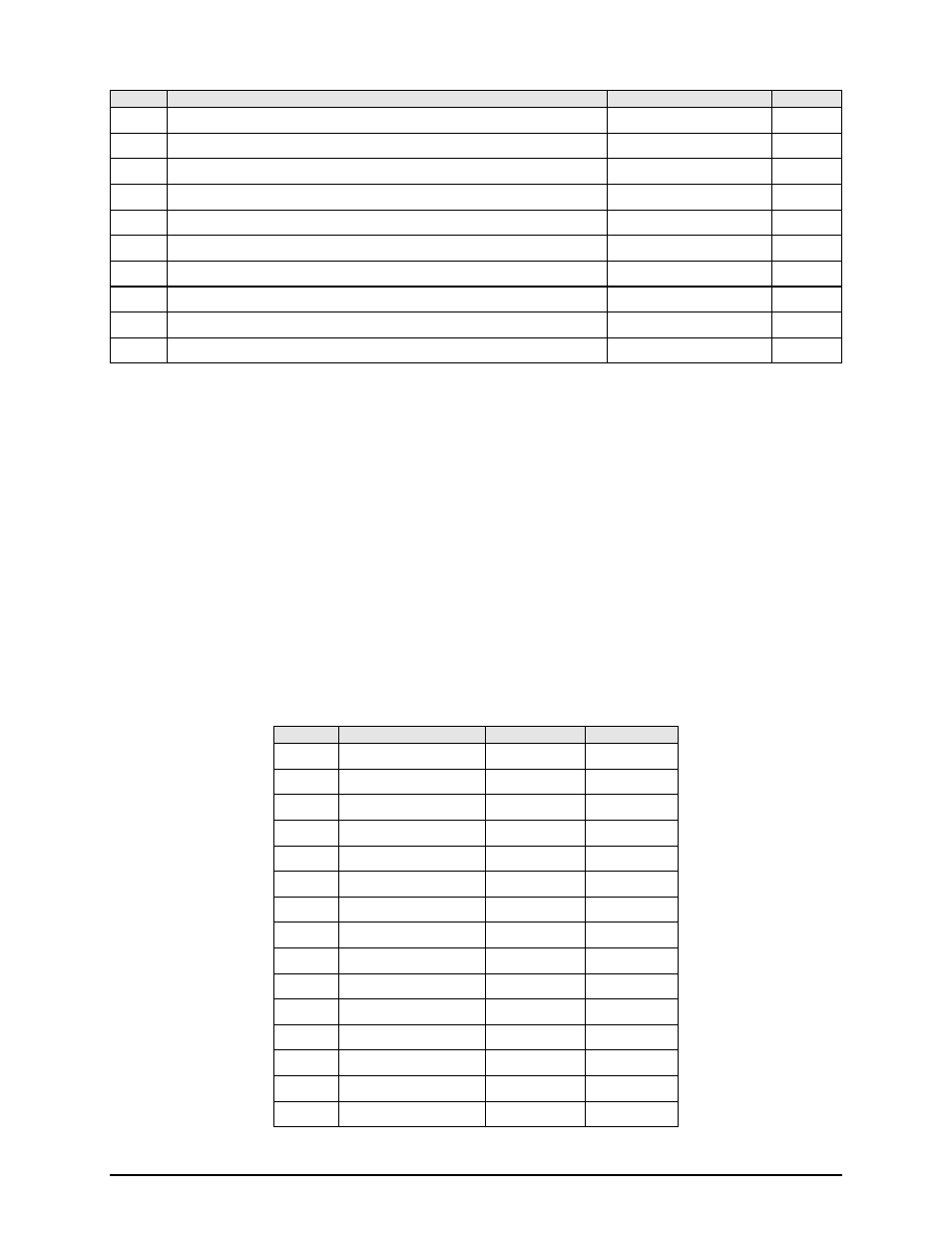
Pin No.
Signal Name
Signal
Direction
59
IDR ESC Transmit 8 Kbps Output Data B
ESCTXD-B
Input
60
IDR ESC Receive 8 Kbps Clock Output B
ESCRXC-B
Output
61
IDR ESC Receive 8 Kbps Data Output B
ESCRXD-B
Output
62
IDR ESC Backward Alarm Out 4 Normally Open
ESCBWO 4NO
---
63
IBS Transmit Octet Input B
TXO-B
Input
64
Synchronous Data Data Mode Out B
SYNC DM-B
Output
65
Synchronous Data Clear to Send B
SYNC CS-B
Input
66
IBS Receive Octet Output B
RXO-B
Output
67
Synchronous Data Request to Send B
SYNC RS-B
Input
68
Synchronous Data Receiver Ready B
SYNC RR-B
Output
5.3.2.2 J9 | MODEM 9 | BACK UP 2 68-Pin High Density Min DSUB Connector
J9 | MODEM 9 | BACK UP 2 connects to Backup Modem 2 in a 2:N configuration, or to the prime modem
9 in a 1:9 configuration. See section 5.3.2.1for pinout table.
5.3.2.3 J10 | BACK UP 1 68-Pin High Density Min DSUB Connector
J10 | BACK UP 1 always connects to backup modem 1 since there is always at least one backup modem
in a redundancy system. See section 5.3.2.1for pinout table.
5.3.2.4 J31 | RCU-20 15-pin High-Density DSUB Connector
J31 | RCU-20 connects the DDS20 to the RCU20 providing power, ground, and serial control.
Pin No.
Signal Name
Signal
Direction
1
Serial Control Clock
DDS_LCLK
IN
2
Relay +6 Volts
VCC_RELAY
IN
3
Serial Control Data 2 DDS_LDAT2 Bidirectional
4
Ground
GND
---
5
Ground
GND
---
6
Logic +5 Volts
VCC
IN
7
Relay +6 Volts
VCC_RELAY
IN
8
Relay +6 Volts
VCC_RELAY
IN
9
Ground
GND
---
10
Ground
GND
---
11
Relay +6 Volts
VCC_RELAY
IN
12
Serial Control Data 1 DDS_LDAT1 Bidirectional
13
Ground
GND
---
14
Serial Control Data 3 DDS_LDAT3 Bidirectional
15
DDS20 Interrupt
INT
OUT