2 rcu20 back panel connectors, 1 slide-out redundant power supply/switch modules, 2 chassis ground – Comtech EF Data RCS20 User Manual
Page 102
RCS20 M:N Redundancy Switch
Revision 15
Electrical Interfaces
MN-RCS20 and CD-RCS20
5–2
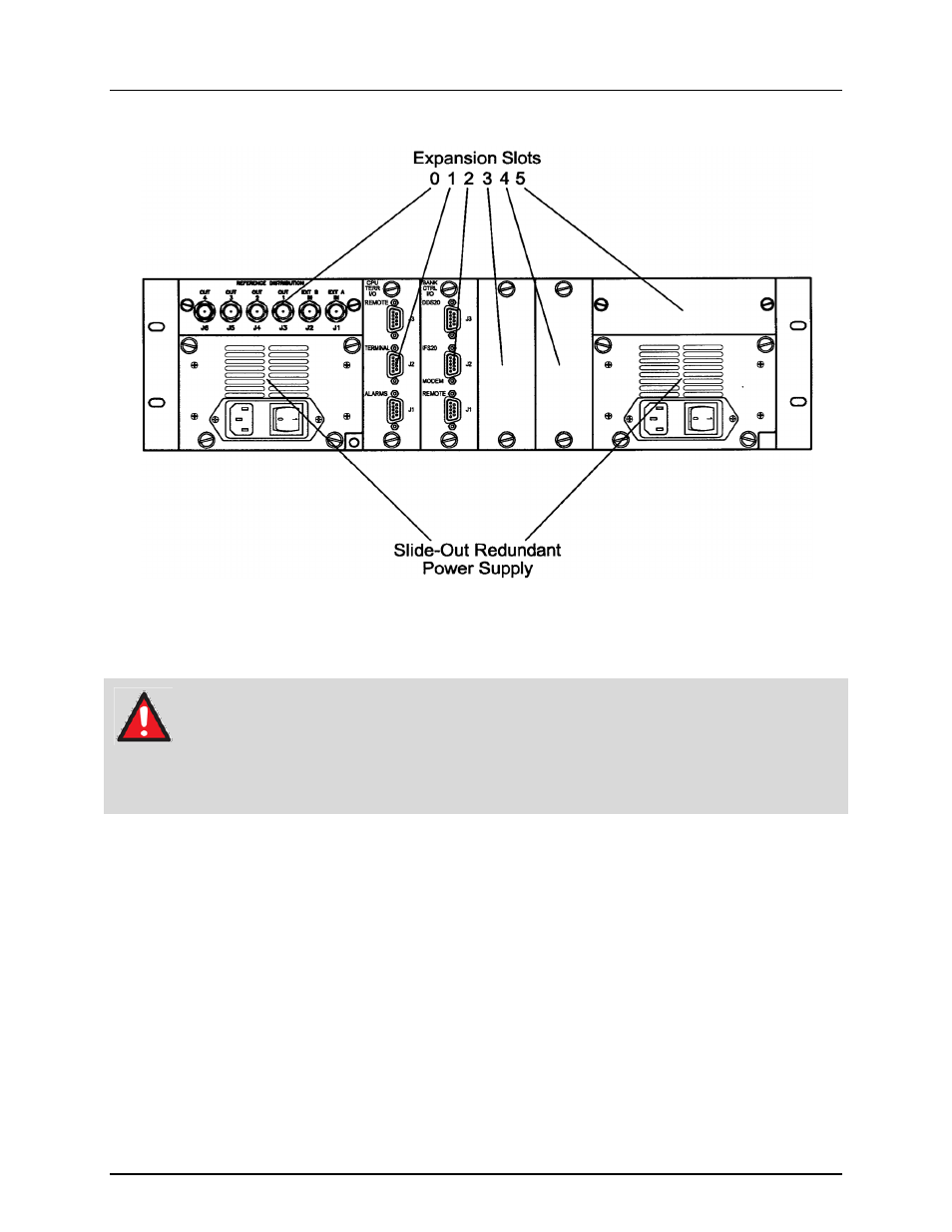
5.2 RCU20 Back Panel Connectors
Figure 5-2 RCS20 Connectors
5.2.1 Slide-Out Redundant Power Supply/Switch Modules
WARNING
Dangerous AC voltages exist inside of the RCS20 when either one of the AC Plug-
in Switch Modules are enabled or plugged in. Do not remove cover when AC power
is applied. Remove power cord from AC modules if top cover needs to be removed.
There are two Slide-Out Redundant Power Supply/Switch Modules located on the left and right sides of
the unit (as shown in Figure 5-2). Power applied to the port with the supplied power cable is 100-240VAC,
50-60 Hz. Each Power Input Module provides an integrated Power On/Off Rocker Switch. Power
consumption for the unit is 1A.
5.2.2 Chassis Ground
A #10-32 threaded stud is located to the lower right of the left hand module for the chassis ground
connection.
- CDD-880 (124 pages)
- CDM-800 (130 pages)
- ODMR-840 (184 pages)
- CDM-750 (302 pages)
- CDM-840 (244 pages)
- SLM-5650A (420 pages)
- CTOG-250 (236 pages)
- CDM-700 (256 pages)
- CDM-760 (416 pages)
- CDM-710G (246 pages)
- CDM-600/600L (278 pages)
- CDMR-570L (512 pages)
- CDM-625 (684 pages)
- CDM-625A (756 pages)
- CDD-564A (240 pages)
- CDD-564L (254 pages)
- CLO-10 (134 pages)
- MCED-100 (96 pages)
- CDMR-570AL (618 pages)
- CDM-600 LDPC (2 pages)
- BUC Power Supply Ground Cable (2 pages)
- MPP70 Hardware Kit for CDM-570L (4 pages)
- MPP50 Hardware Kit for CDM-570L (4 pages)
- CDM-625 DC-AC Conversion (4 pages)
- CDM-625 DC-AC Conversion with IP Packet Processor (4 pages)
- DMDVR20 LBST Rev 1.1 (117 pages)
- DMD2050E (212 pages)
- DMD-2050 (342 pages)
- DMD1050 (188 pages)
- OM20 (220 pages)
- QAM256 (87 pages)
- DD240XR Rev Е (121 pages)
- MM200 ASI Field (5 pages)
- DM240-DVB (196 pages)
- MM200 (192 pages)
- CRS-150 (78 pages)
- CRS-280L (64 pages)
- CRS-170A (172 pages)
- CRS-180 (136 pages)
- SMS-301 (124 pages)
- CiM-25/8000 (186 pages)
- CiM-25 (26 pages)
- CRS-500 (218 pages)
- CRS-311 (196 pages)
- CIC-20 LVDS to HSSI (26 pages)