Table 4-19. vtx connection settings -31 – Basler Electric BE1-700 User Manual
Page 87
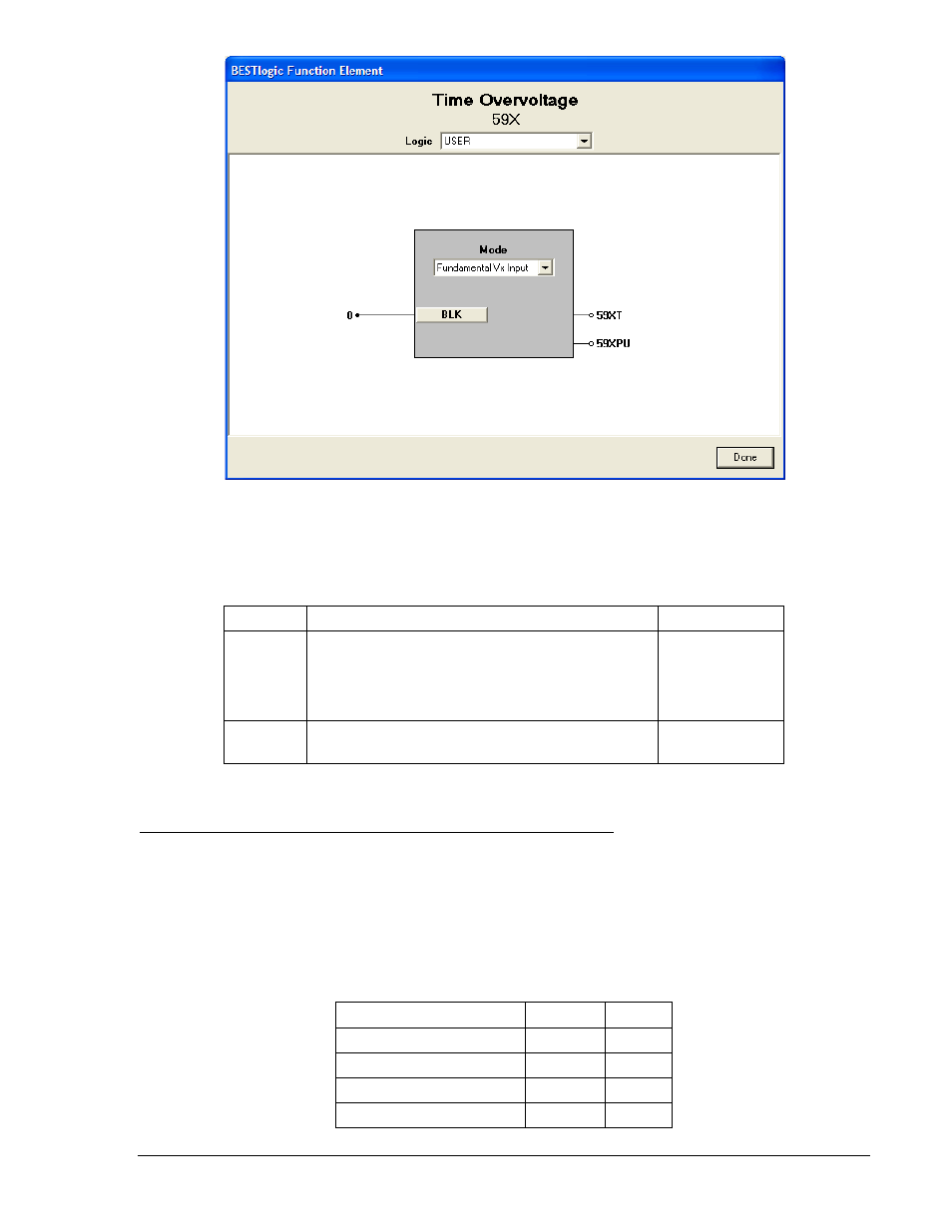
Figure 4-26. BESTlogic Function Element Screen, 59X
Table 4-18 summarizes the BESTlogic settings for Auxiliary Undervoltage/Overvoltage Protection.
Table 4-18. BESTlogic Settings for Auxiliary Undervoltage/Overvoltage Protection
Function
Range/Purpose
Default
Mode
0 = Disabled
1 = Fundamental Vx Input
2 = 3Vo Phase Inputs
∗
3 = 3
rd
Harmonic, Vx Input
0
BLK
Logic expression that disables function when
TRUE. A setting of 0 disables blocking.
0
∗ To use Mode 2, the VTP connection must be 4-wire. Optional Auxiliary Input must be present to use
Mode 1 or Mode 3.
Operating Settings for Auxiliary Undervoltage/Overvoltage Protection
Operating settings for the 27X and 59X functions consist of pickup and time delay values. The pickup
value determines the level of voltage required for the element to start timing toward a trip. Unit of measure
is secondary volts (PP or PN) and depends on the VTX setting see Table 4-19. For more information,
refer to Section 3, Input and Output Functions, Power System Inputs, Voltage Measurement. The time
delay value determines the length of time between pickup and trip. Time delays can be set in
milliseconds, seconds, or cycles. The default is milliseconds if no unit of measure is specified.
Table 4-19. VTX Connection Settings
VTX Connection
Mode
Unit
AB, BC, CA
1 or 3
VPP
AN, BN, CN
1 or 3
VPN
GR
1 or 3
VPN
Don’t care
2
VPN
9376700990 Rev M
BE1-700 Protection and Control
4-31