Table 13-59. x81 pickup test commands -37, Table 13-60. x81 pickup and mode settings -37, N table – Basler Electric BE1-700 User Manual
Page 333
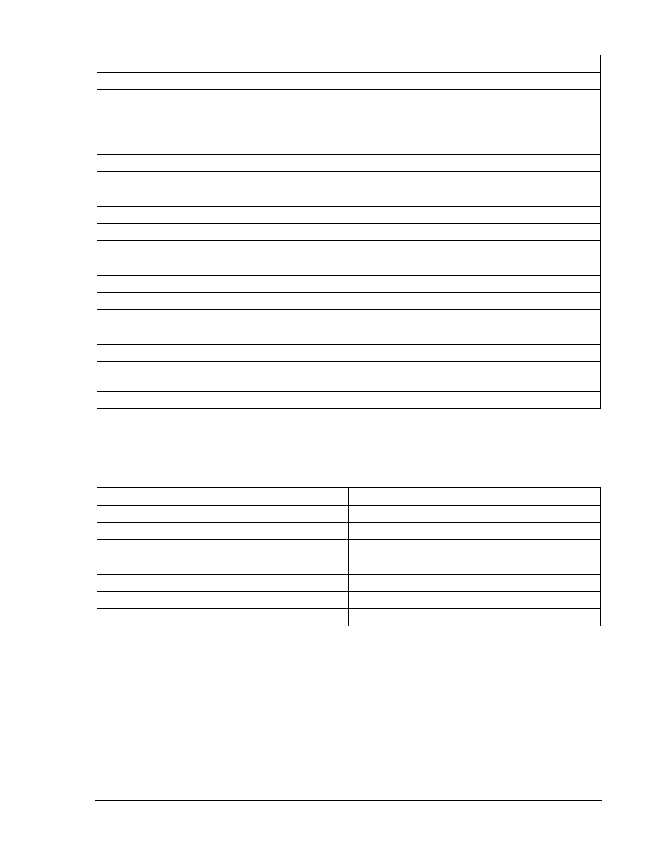
Table 13-59. x81 Pickup Test Commands
Command
Purpose
A=
Gains write access.
SL-N=NONE
Zero out custom logic settings. Overwrite with
LOGIC=NONE settings.
Y
Confirm overwrite.
SL-N=FREQTEST
Sets FREQTEST as custom logic name.
SL-81=1,0
Enables 81, disables blocking.
SL-181=1,0
Enables 181, disables blocking.
SL-281=1,0
Enables 281, disables blocking.
SL-381=1,0
Enables 381, disables blocking.
SL-481=1,0
Enables 481, disables blocking.
SL-581=1,0
Enables 581, disables blocking.
SL-VO1=81T+581T
Enables OUT1 to close for 81 or 581 trip.
SL-VO2=181T
Enables OUT2 to close for 181 trip.
SL-VO3=281T
Enables OUT3 to close for 281 trip.
SL-VO4=381T
Enables OUT4 to close for 381 trip.
SL-VO5=481T
Enables OUT5 to close for 481 trip.
SG-TARG=81/181/281/381/481/581
Enables 81, 181, 281, 381, 481, and 581 targets.
SG-
TRIG=81T+181T+281T+381T+481T+581T
Sets fault trigger on any x81.
EXIT;Y
Exit and save settings.
Step 2: Transmit the commands in Table 13-60 to the relay. These commands set the voltage inhibit
value, pickup value, and operating mode (Underfrequency or Overfrequency) for each of the
x81 functions.
Table 13-60. x81 Pickup and Mode Settings
Pickup and Mode Settings
Purpose
S0-81INH=40
Set PU = 40V
S0-81=42,0,U
Sets 81 PU at 42 Hz, Underfrequency.
S0-181=46,0,U
Sets 181 PU at 46 Hz, Underfrequency.
S0-281=48,0,U
Sets 281 PU at 48 Hz, Underfrequency.
S0-381=65,0,O
Sets 381 PU at 65 Hz, Overfrequency.
S0-481=67,0,O
Sets 481 PU at 67 Hz, Overfrequency.
S0-581=69,0,O
Sets 581 PU at 69 Hz, Overfrequency.
Step 3: Prepare to monitor x81 function operation. Operation can be verified by monitoring the
programmed output contacts or HMI Screen 1.5.2.
Step 4: Connect and apply a 120 Vac, 60-hertz voltage source to Terminals C13 (A-phase) and C16
(neutral).
Step 5: Slowly decrease the frequency of the applied voltage until OUT3 (281) closes. Pickup should
occur within
±0.01 hertz of the pickup setting. Slowly increase the frequency until OUT3 opens.
Dropout should occur at 0.02 hertz above or below the pickup setting.
Step 6: Lower the frequency until OUT3 again closes. Lower the source voltage until OUT3 drops out
(under voltage inhibit level), raise the voltage until OUT3 picks up. Pickup should occur
±2% of
the voltage inhibit setting and drop out at 95% of pickup.
9376700990 Rev M
BE1-700 Testing and Maintenance
13-37