Virtual switches (43), Virtual switches (43) -42, Table 13-68. bf pickup limits -42 – Basler Electric BE1-700 User Manual
Page 338: Table 13-69. bf time delay commands -42
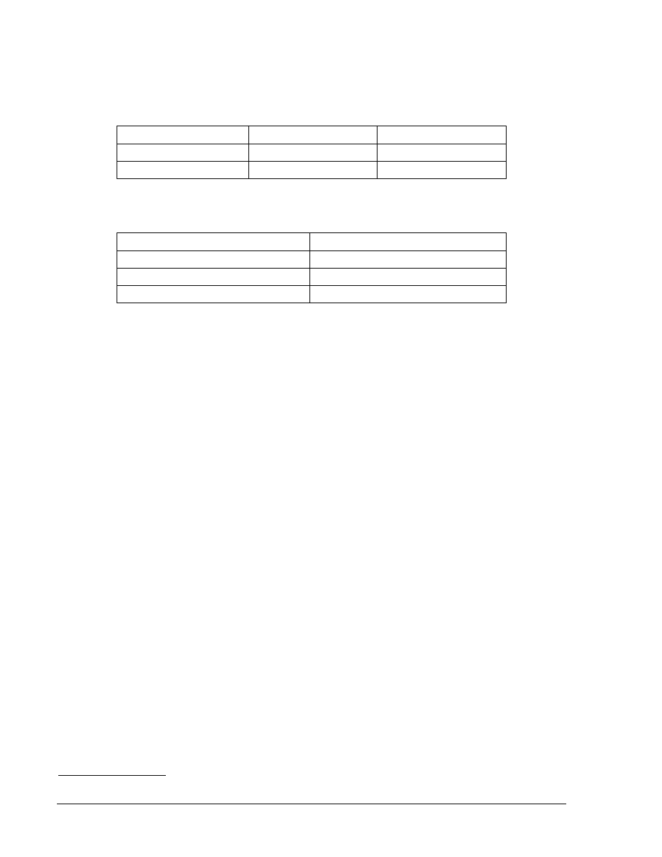
Step 3: Connect a current source to Terminals D1 and D2 (A-phase input). Slowly increase the current
applied to the A-phase input until OUT2 (and subsequently OUT1) closes. Compare the applied
current to the current values listed in Table 13-68. Verify that pickup occurred between the
lower and upper limits for your relay.
Table 13-68. BF Pickup Limits
Sensing Type
Lower PU Limit
Upper Pickup Limit
B (1 A)
0.09 A
0.11 A
E or F (5 A)
0.45 A
0.55 A
Step 4: Transmit the commands in Table 13-69 to set the BF time delay.
Table 13-69. BF Time Delay Commands
Command
Purpose
A=
Gains write access.
SP-BF=100m
Set BF time delay at 100 milliseconds.
EXIT;Y
Exit and save settings.
Step 5: Verify the BF time delay by applying the pickup current obtained in Step 3 for the duration given
in the following steps:
A. Apply pickup current to phase A for 4 cycles (67 ms at 60 Hz). No trip should occur.
B. Apply pickup current to phase A for 5 cycles (83 ms at 60 Hz). No trip should occur.
C. Apply pickup current to phase A for 7 cycles (117 ms at 60 Hz). A BF trip should
occur. Use the RS-LGC command to retrieve an SER report and verify that a BF trip
was logged 100 milliseconds
±5% (+11/4, -1/4) after application of pickup current.
Step 6: (Optional.) De-energize relay Input IN3. This will block the breaker fail logic and cause OUT1
and OUT2 to open. Verify that relay outputs OUT1 and OUT2 remain open (BF element does
not operate) even though pickup current is applied. De-energize IN3 and verify that OUT2 (and
subsequently OUT1) closes. Remove current from phase A.
Step 7: (Optional.) Apply pickup current to phase A. OUT2 and OUT1 should close. De-energize IN4
and verify that OUT1 and OUT2 open. Remove current from phase A.
Step 8: Energize IN4 and apply 0.7 A of current to the phase A current input and measure the time
between the application of current and OUT1 closing. OUT2 should have closed immediately
when current was applied. Verify that the BF Timer operated within the specified accuracy of
±5% or +11/4, -1/4 cycles, whichever is greater.
Step 9: (Optional.) Repeat Steps 3 through 8 for the phase B and phase C elements.
Virtual Switches (43)
Purpose: To verify operation of the 43/143 virtual switches.
Reference Commands: SL-43/143, CS/CO-43/143
To test virtual switches, we verify each mode of operation but you do not have to verify both of the virtual
switches. In your testing, you may use either of the switches, as desired. If you give an invalid command
such as CS-143=1/CO-143=1 when Switch 143 is programmed for Mode 3 operation, the relay will reject
the command and return an INVALID PARAMETER message through the ASCII command interface. For
more information about virtual switch operation, see Section 4, Protection and Control, Virtual Switches.
You may verify operation of virtual switches by monitoring the programmed output contacts, HMI Screen
1.5.4, or by using the RS-LGC command to retrieve logic variable data from the SER. You also may use
the RG-STAT command. See Section 6, Reporting and Alarm Functions, for more information about
reports.
Mode 1 - On/Off/Pulse
Step 1: Prepare the x43 virtual switch for Mode 1 testing by transmitting the commands in Table 13-70.
13-42
BE1-700 Testing and Maintenance
9376700990 Rev M