Basler Electric BE1-700 User Manual
Page 78
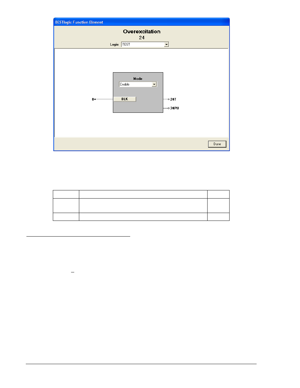
Figure 4-16. BESTlogic Function Element Screen, 24
Table 4-13 lists the BESTlogic settings for Overexcitation Protection.
Table 4-13. BESTlogic Settings for Volts per Hertz Overexcitation
Function
Range/Purpose
Default
Mode
0 = Disable
1 = Enable
0
BLK
Logic expression that disables the function when TRUE.
0
Operating Settings for Overexcitation Protection
Operating settings for the 24 function consist of a pickup setting, a trip time dial, and a reset time dial. A
pickup of 0 disables the element. The unit of measure is secondary VPP/Hz or VPN/Hz and depends on
the SG-VTP setting. For more information, refer to Section 3, Input and Output Functions, Power System
Inputs. Operating settings are made using BESTCOMS. Figure 4-17 illustrates the BESTCOMS screen
used to select operational settings for the Overexcitation element. To open the screen, select Voltage
Protection from the Screens pull-down menu and select the 24 Tab. Alternately, settings can be made
using the S
equals 1 or 2, for Setting Group 0 or 1.
4-22
BE1-700 Protection and Control
9376700990 Rev M