Basler Electric BE1-700 User Manual
Page 321
Step 2: Using Table 13-32 as a guide, transmit the setting commands to the relay.
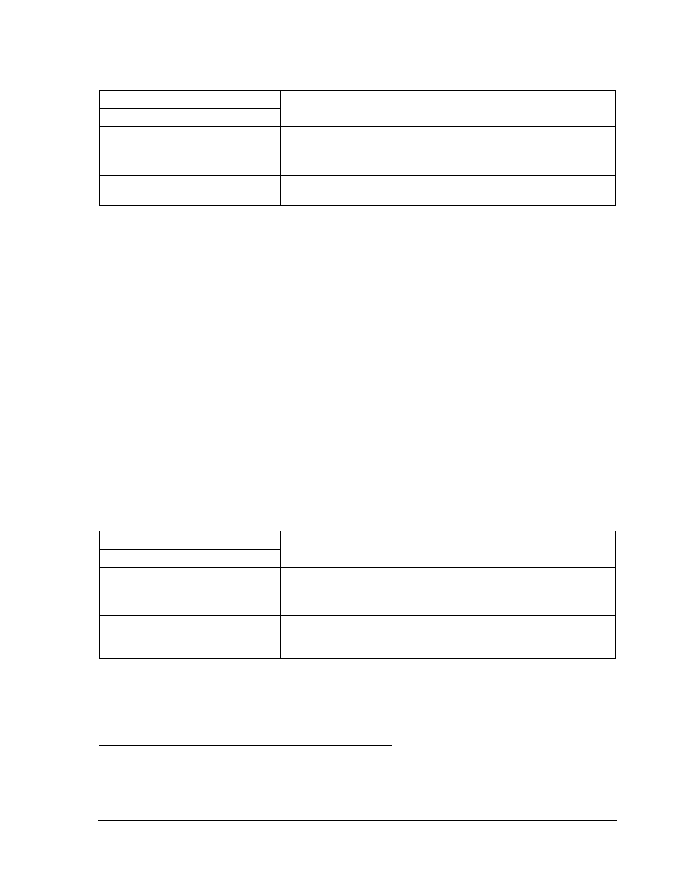
Table 13-32. Alarm, Integrating Time, and Definite Time Pickup Settings (Step 2)
Overexcitation Settings
Purpose
Pickup
SA-24=2.05,0.0
Sets 24 Alarm at 1.025% of nominal (2.05 V/Hz), Time Delay = 0.
S0-24=2.1,0.0,0.0,2.0
Sets 24 Integrating PU at 1.05% of nominal (2.10 V/Hz), Trip
Time Dial = 0, Reset Time Dial = 0, Time Curve Exponent = 2.
S0-24D=0.0,50ms,0.0,50ms
Sets 24 Definite Time, Pickups at 0 and Definite Time, Time
Delay at minimum.
Step 3: Prepare to monitor the operation of the 24 Alarm and Trip functions. Alarm operation can be
verified by monitoring the Major Alarm LED on the relay's front panel. Operation of 24T by can
be verified by monitoring OUT1.
Step 4: Connect a 120 Vac, three-phase, 50 or 60-hertz voltage source (depending on user's nominal
frequency) to Terminals C13 (A-phase), C14 (B-phase), C15 (C-phase), and C16 (neutral).
Refer to Figure 12-4 for terminal locations.
Step 5: Apply A-phase voltage at nominal frequency and slowly increase until the Major Alarm LED
lights (V/H PU x Freq x % Alarm = PU). Pickup should occur within
±2 percent or 1 volt of the
Alarm setting. Continue increasing the A-phase voltage until OUT1 closes (V/H Trip x Freq =
PU). Pickup should occur within
±2 percent or 1 volt of the Trip pickup setting. Slowly decrease
the A-phase voltage until OUT1 opens. Dropout should occur at 95% or higher of the actual
pickup value for both Trip and Alarm.
Step 6: Verify the 24 target on the HMI.
Step 7: (Optional.) Repeat Steps 2 through 6 for higher and lower alarm and trip pickup settings.
Step 8: (Optional.) Repeat Steps 2 through 6 for frequencies other than nominal.
Step 9: (Optional.) Repeat Steps 2 through 8 for the B-phase and C-phase voltage inputs.
Step 10: (Optional.) Repeat Steps 2 through 9 for Setting Group 1.
Step 11: Using Table 13-33 as a guide, transmit the setting commands to the relay.
Table 13-33. Alarm, Integrating Time, and Definite Time Pickup Settings (Step 11)
Overexcitation Settings
Purpose
Pickup
SA-24=0,0.0
Sets 24 Alarm = 0, Time Delay = 0.
S0-24=0.0,0.0,0.0,2.0
Sets 24 Integrating PU =0, Trip Time Dial = 0, Reset Time Dial =
0, Time Curve Exponent = 2.
S0-24D=2.36,50ms,0.0,50ms
Sets the first 24 Definite Time Pickup at 118% of nominal (2.36
V/Hz) and Definite Time Delay at minimum. Set second 24
Definite Time Pickup = 0 and Definite Time Delay at minimum.
Step 12: Repeat Steps 2 through 10 for the first definite time pickup.
Step 13: Using Table 13-33 as a guide, set first definite time setting to 0 and second to 2.36 V/Hz.
Step 14: Repeat Steps 2 through 10 for the second definite time delay.
Overexcitation, Volts/Hertz Integrating Trip Time Verification
The following test uses the (M-1)^2 time curve.
Step 1: Using Table 13-34 as a guide, transmit the setting commands to the relay.
9376700990 Rev M
BE1-700 Testing and Maintenance
13-25