General, Contact-sensing inputs, Mounting – Basler Electric BE1-700 User Manual
Page 271: Case cutouts and dimensions, Section 12, Installation -1, General -1, Contact-sensing inputs -1, Mounting -1, Case cutouts and dimensions -1
SECTION 12
• INSTALLATION
GENERAL
BE1-700 Digital Protective Relays are delivered with an instruction manual and BESTCOMS
™ software in
a sturdy carton to prevent shipping damage. Upon receipt of the relay, check the model and style number
against the requisition and packaging list for agreement. If there is evidence of shipping damage, file a
claim with the carrier and notify Basler Electric Regional Sales Office, your sales representative, or a
sales representative at Basler Electric, Highland, Illinois.
If the BE1-700 is not installed immediately, store it in the original package in a moisture and dust free
environment.
CONTACT-SENSING INPUTS
Four contact-sensing inputs provide external stimulus to initiate BE1-700 actions. An external wetting
voltage is required for the contact-sensing inputs. The nominal voltage level of the external dc source
must comply with the dc power supply input voltage ranges listed in Section 1, General Information,
General Specifications. In addition, Section 1, Figure 1-1 indicates the power supply options available
with your type of relay.
Energizing levels for the contact sensing inputs are for a minimum of approximately 5 Vdc for 24 Vdc
nominal sensing voltages, 26 Vdc for 48 Vdc nominal sensing voltages, 69 Vdc for 125 Vdc nominal
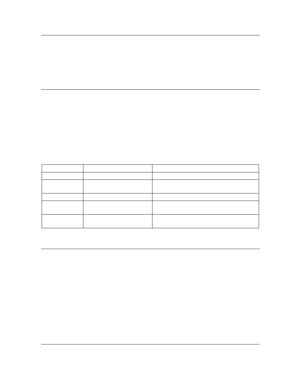
sensing voltages, or 138 Vdc for 250 Vdc nominal sensing voltages. See Table 12-1 for the contact-
sensing turn-on voltages.
Table 12-1. Contact-Sensing Turn-On Voltages
Style Option
Nominal Input Voltage
Contact-Sensing Turn-On Voltage †
xxx1xxx
48 Vdc
26 to 38 Vdc
xxx2xxx
125 Vac/dc
69 to 100 Vdc
56 to 97 Vac
xxx3xxx
24 Vdc
Approx. 5 Vdc
xxx4xxx
250 Vac/dc
138 to 200 Vdc
112 to 194 Vac
xxx5xxx
125 Vac/dc
*
69 to 100 Vdc
56 to 97 Vac
* Extended holdup option. See Style Chart in Figure 1-1.
† AC voltage ranges are calculated using the default recognition time (4 ms) and debounce time (16 ms).
MOUNTING
Basler numeric relays are supplied in a Basler Electric “X” case. This is a panel-mount, non-drawout case
that is mounted horizontally.
Case Cutouts and Dimensions
The case dimensions are shown in Figure 12-1. Mounting plate cutout and drilling dimensions for the
relay are shown in Figure 12-2.
9376700990 Rev M
BE1-700 Installation
12-1