Figure 4-17. voltage protection screen, 24 tab -23 – Basler Electric BE1-700 User Manual
Page 79
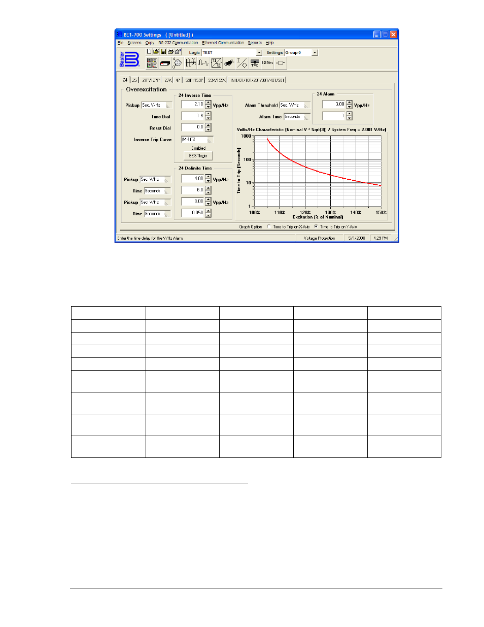
Figure 4-17. Voltage Protection Screen, 24 Tab
Table 4-14 lists the operating settings for Overexcitation Protection.
Table 4-14. Operating Settings for Overexcitation Protection
Setting
Range
Increment
Unit of Measure
Default
Integrating Pickup
0.5 to 6
0.1
Sec. V/Hz
0
Trip Time Dial
0 to 9.9
0.1
N/A
0
Reset Time Dial
0 to 9.9
0.1
N/A
0
Inverse Trip Curve
0.5, 1.0, 2.0
N/A
N/A
(M-1)^2
Definite Time
Pickup #1
0.5 to 6
0.1
Sec. V/Hz
0
Definite Time
Delay #1
0.050 to 600
3 digit resolution
Seconds
50 ms
Definite Time
Pickup #2
0.5 to 6
0.1
Sec. V/Hz
0
Definite Time
Delay #2
0.050 to 600
3 digit resolution
Seconds
50 ms
Programmable Alarm for Overexcitation Protection
A separate V/Hz alarm threshold and user adjustable time delay are included for indicating when
overexcitation is occurring so that the operator can take corrective action before the 24 function trips. If
the V/Hz level exceeds the alarm setting, a programmable alarm bit is set. See Section 6, Reporting and
Alarm Functions, for more information. Settings for the alarm are made using BESTCOMS (Figure 4-17).
Alternately, settings can be made with the SA-24 ASCII command. Table 4-15 lists the programmable
alarm settings for Overexcitation. V/Hz alarm settings cannot be set through the HMI.
9376700990 Rev M
BE1-700 Protection and Control
4-23