Basler Electric BE1-700 User Manual
Page 327
Step 3: Continue to decrease the voltage until OUT1 opens. UV inhibit pickup should occur within
±3
percent of 50V. Increase the voltage until OUT1 closes. UV inhibit dropout should occur at
±5
percent of inhibit pickup.
Step 4: (Optional.) Repeat Steps 1 through 3 for Setting Group 1.
Auxiliary Undervoltage and Overvoltage Timing Verification (3V0 VT Input)
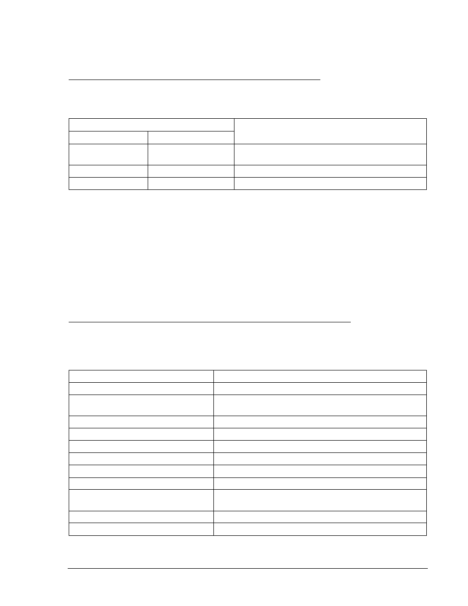
Step 1: Using Table 13-47as a guide, transmit the first row of setting commands to the relay.
Table 13-47. 27X and 59X/159X Pickup and Time Delay Settings (3V0)
Pickup Settings
Purpose
Undervoltage
Overvoltage
S0-27X=10,2S,0
S0-59X/159X=30,2S
Sets 27X PU at 10 V, 59X/159X at 30 V, TD at 2 sec,
UV Inhibit disabled.
S0-27X=,5S
S0-59X/159X=,5S
Sets 27X PU at 10 V, 59X/159X at 30 V, TD at 5 sec.
S0-27X=,10S
S0-59X/159X=,10S
Sets 27X PU at 10 V, 59X/159X at 30 V, TD at 10 sec.
Step 2: Prepare to monitor the 27X and 59X/159X timings. Timing accuracy is verified by measuring the
elapsed time between a sensing voltage change and OUT1 closing.
Step 3: Connect and apply a single-phase, 20 Vac to Terminals C13 (polarity) and C16 (non-polarity).
Refer to Figure 12-4 for terminal locations.
Step 4: Step the voltage down to 5 volts. Measure the time delay and verify the accuracy of the 27X
time delay setting. Timing accuracy is
±5 percent or ±3 cycles of the time delay setting.
Step 5: Step the voltage up to 35 volts. Measure the time delay and verify the accuracy of the 59X/159X
time delay setting. Timing accuracy is
±5 percent or ±3 cycles of the time delay setting.
Step 6: Repeat Steps 5 and 6 for the middle and upper time delay settings of Table 13-47.
Step 7: (Optional.) Repeat Steps 2 through 6 for Setting Group 1.
Auxiliary Undervoltage and Overvoltage Pickup Verification (Fundamental Vx Input)
Step 1: Prepare the 27X and 59X/159X pickup functions for testing by transmitting the commands in
Table 13-48 to the relay. Reset targets.
Table 13-48. 27X and 59X/159X Pickup Test Commands
Command
Purpose
A=
Gains write access.
SL-N=NONE
Zero out custom logic settings. Overwrite with
LOGIC=NONE settings.
Y
Confirm overwrite.
SL-N=27X_59X/159X
Sets 27X_59X/159X as custom logic name.
SG-VTX=1,AN
Set auxiliary voltage parameters.
SL-27X=1,0
Enables 27X, disables blocking.
SL-59X/159X=1,0
Enables 59X and 159X, disables blocking.
SL-VO1=27XT+59XT+159XT
Enables OUT1 to close for 27X, 59X, or 159X trip.
SG-TRIG=27XT+59XT+159XT,
27XPU+59XPU+159XPU
Enables 27XT, 59XT, or 159XT to log and trigger fault
recording.
SG-TARG=27/59/159
Enables 27X, 59X, and 159X targets.
EXIT;Y
Exit and save settings.
9376700990 Rev M
BE1-700 Testing and Maintenance
13-31