Auxiliary voltage input verification - vx and vx 3, Fundamental and third harmonic) (be1-700v), Table 13-4. voltage circuit verification values -7 – Basler Electric BE1-700 User Manual
Page 303: Values -7
Step 4: Connect relay Terminals C13 (A-phase), C14 (B-phase), and C15 (C-phase) together. Connect
an ac voltage source at nominal frequency to the three jumpered terminals and the Neutral
Terminal (C16).
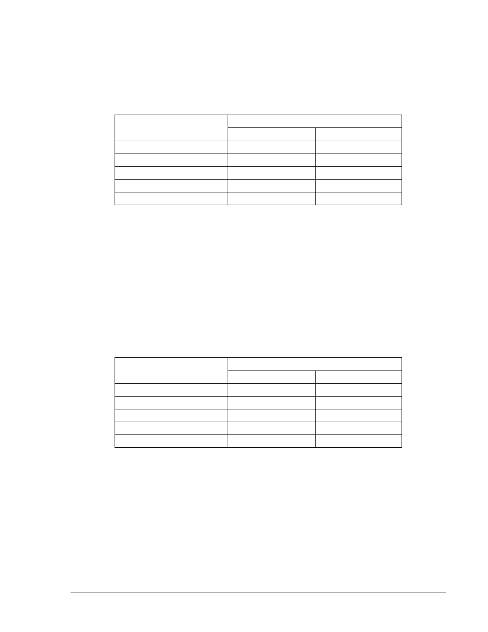
Step 5: Apply the voltage values listed in Table 13-4 and verify voltage measuring accuracy by
transmitting the M command to the relay. HMI Screen 3.1 can also be monitored to verify
voltage measurements or the Metering screen of BESTCOMS.
Table 13-4. Voltage Circuit Verification Values
Applied Voltage
Measured Voltage
Lower Limit
Upper Limit
80 volts
79.2 V
80.8 V
100 volts
99.0 V
101.0 V
120 volts
118.8 V
121.2 V
140 volts
138.6 V
141.4 V
160 volts
156.8 V
163.2 V
Auxiliary Voltage Input Verification - VX and VX 3
rd
(Fundamental and Third Harmonic) (BE1-700V)
Step 1: Connect relay Terminals C17 (polarity) and C18 to a 60 hertz ac voltage source.
Step 2: Apply the voltage values listed in Table 13-5 and verify voltage-measuring accuracy by
transmitting the M-V command to the relay. BESTCOMS Metering or HMI Screens 3.3 can also
be monitored to verify VX voltage measurements.
Step 3: Connect relay Terminals C17 (polarity) and C18 to a 180-hertz (third harmonic) ac voltage
source.
Step 4: Apply the voltage values listed in Table 13-5 and verify voltage-measuring accuracy by
transmitting the M command to the relay. BESTCOMS Metering or HMI Screen 3.3 can also be
monitored to verify VX voltage measurements.
Table 13-5. Aux Voltage Circuit Verification VX & VX 3
rd
Values
Applied Voltage
Measured Voltage
Lower Limit
Upper Limit
5 Vac
4.95 Vac
5.05 Vac
20 Vac
19.8 Vac
20.2 Vac
60 Vac
59.4 Vac
60.6 Vac
80 Vac
79.2 Vac
80.8 Vac
120 Vac
118.8 Vac
121.2 Vac
Line and Bus Angle, Frequency, and Slip Verification
• Connect relay Terminals C13 (polarity) and C16 (A to Neutral of the three-phase voltage input) to
a 60-hertz ac voltage source (line voltage).
• Connect relay Terminals C17 (polarity) and C18 (auxiliary voltage input) to a second 60-hertz ac
voltage source (bus voltage).
• Apply 115 volts at 0 degrees and 60 hertz to both sources. Verify the measuring accuracy of the
line and bus frequency, angle between the two voltages and slip frequency by transmitting the M
command to the relay. HMI Screens 3.10 and 3.11 can also be monitored to verify the
measurements.
• Vary the angle of the line voltage and verify the measured angle as in Step 3. Polarity of the
angle measurement is relative to the angle of the line voltage. That is, if the line voltage lags the
9376700990 Rev M
BE1-700 Testing and Maintenance
13-7