Output contact seal-in, Output contact seal-in -41, Figure 8-17. output seal-in logic diagram -41 – Basler Electric BE1-700 User Manual
Page 223
sensing input. Select binary coded setting group selection (Mode 2). If D0 is set, Group 0 will be selected
when the input is off (binary code 00). Group 1 will be selected when the input is on (binary code 01).
Similarly, if D1 is set, Group 2 will be selected when the input is on (binary coded 10).
This logic is useful in a situation where two transformers feed a single bus or two busses have a bus tie
between them. The feeder and bus relays must be coordinated so that only one source is in service (bus
tie open or one transformer out of service). However, when both sources are in service, such as when the
bus tie is closed, each bus relay sees only half of the current for a fault. This results in poor sensitivity and
slow clearing time for the bus relays.
Example 2.
Adapting the logic in different setting groups
The logic in most of the preprogrammed logic schemes can be varied in each of the different setting
groups. This is accomplished by disabling functions by setting their primary settings at zero. It
=s also
possible to perform more sophisticated modification of the logic in each of the different setting groups by
using the active setting group logic variables SG0 and SG1 in the BESTlogic expressions.
Output Contact Seal-In
Trip contact seal-in circuits have historically been provided with electromechanical relays. These seal-in
circuits consists of a dc coil in series with the relay trip contact and a seal-in contact in parallel with the
trip contact. The seal-in feature serves several purposes for electromechanical relays.
1. It provides the mechanical energy to drop the target.
2. It carries the dc tripping current from the induction disk contact which may not have significant closing
torque for a low resistance connection.
3. It prevents the relay contact from dropping out until the current has been interrupted by the 52a
contacts in series with trip coil.
The first two items are not an issue for solid-state relays. But item three is significant.
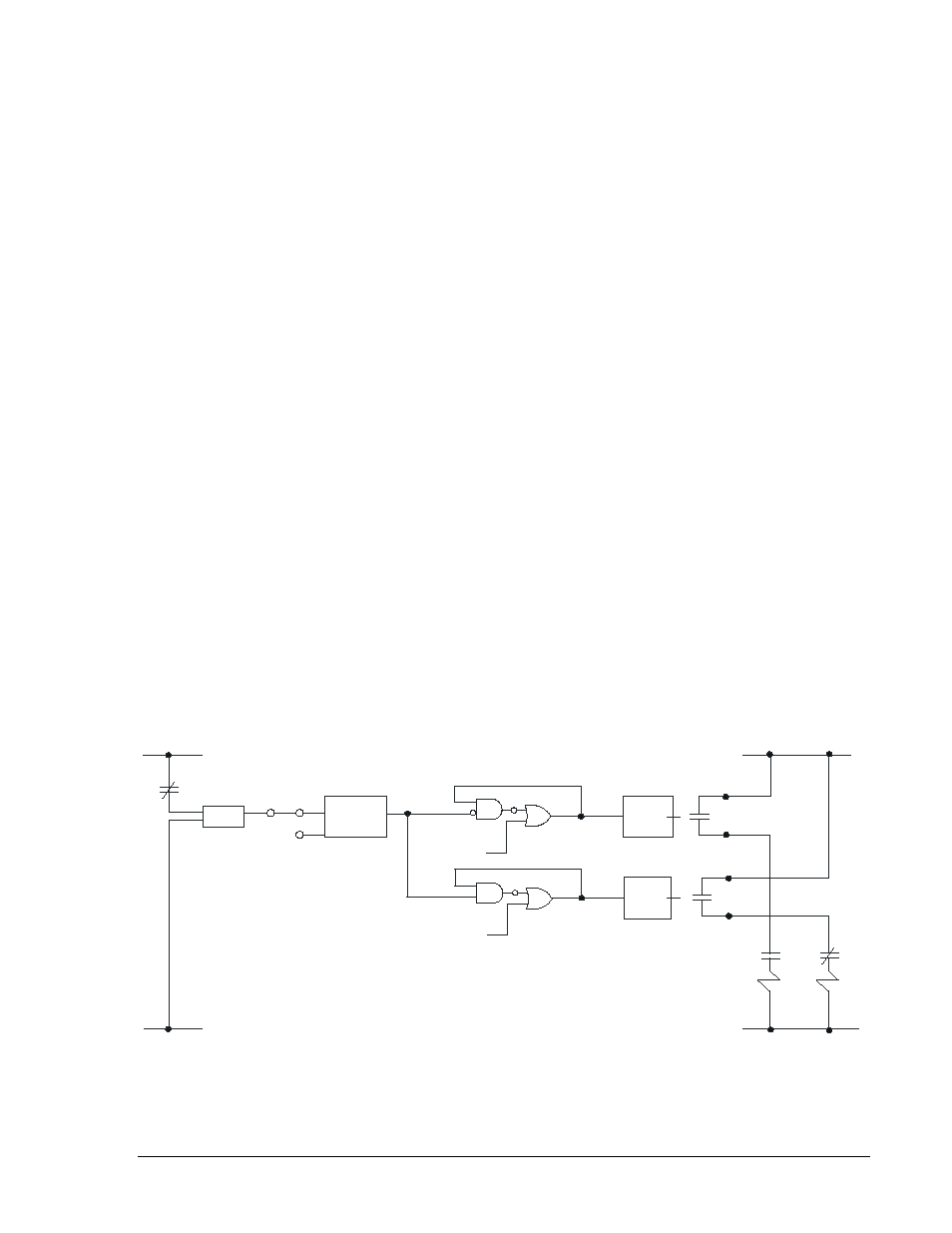
To prevent the output relay contacts from opening prematurely, a 200 millisecond hold timer can be
selected with the SG-HOLDn=1 command. Refer to Section 3, Input and Output Functions, Outputs, for
more information about this feature. If desired, seal-in logic with feedback from the breaker position logic
can be obtained by modifying the BESTlogic expression for the tripping output. To do this, set one of the
general purpose timers (62 or 162) for Mode 1 (Pickup/Dropout Timer). Set the timer logic so that it is
initiated by the breaker position input, and set the timer for two cycles pickup and two cycles dropout.
Then AND the timer output with the tripping output and OR it into the expression for the tripping output.
The same can be done for the closing output. Figure 8-17 illustrates the seal-in logic diagram.
Figure 8-17. Output Seal-In Logic Diagram
OUTPUT
LOGIC
OPTO
OUTPUT
LOGIC
INI
62
BLK
IN1
52b
+
+
62
-
TRIPPING
LOGIC
52TC
CLOSING
LOGIC
52CC
OUT2
OUT1
+
-
52a
52b
52TC
52CC
D2590-10
03-23-98
VO1
VO2
VO7
VO6
9376700990 Rev M
BE1-700 Application
8-41