Current circuit verification (be1-700c), Current circuit verification (be1-700c) -6, Table 13-3. current circuit verification values -6 – Basler Electric BE1-700 User Manual
Page 302
Step 6: Transmit the commands CS-OUT=DIS, CO-OUT=DIS, EXIT, and YES to disable the output
control override capability of the relay.
Current Circuit Verification (BE1-700C)
Step 1: To verify IN and IQ, connect an ac current source to Terminals D1 and D2.
Step 2: Apply the appropriate current values in Table 13-3 to the relay. Measured IN should correspond
to values in Table 13-3 while IQ (negative-sequence current I2) should be 1/3 the applied value
±1.5%. (For example, if the applied value equals 2 amps, IQ = 2/3 = 0.667 amps ±1.5% or ±.01
amps.) Verify current measuring accuracy by transmitting the M command to the relay for each
applied current value. HMI Screen 3.7 also can be used to verify the IN and IQ current
measurements.
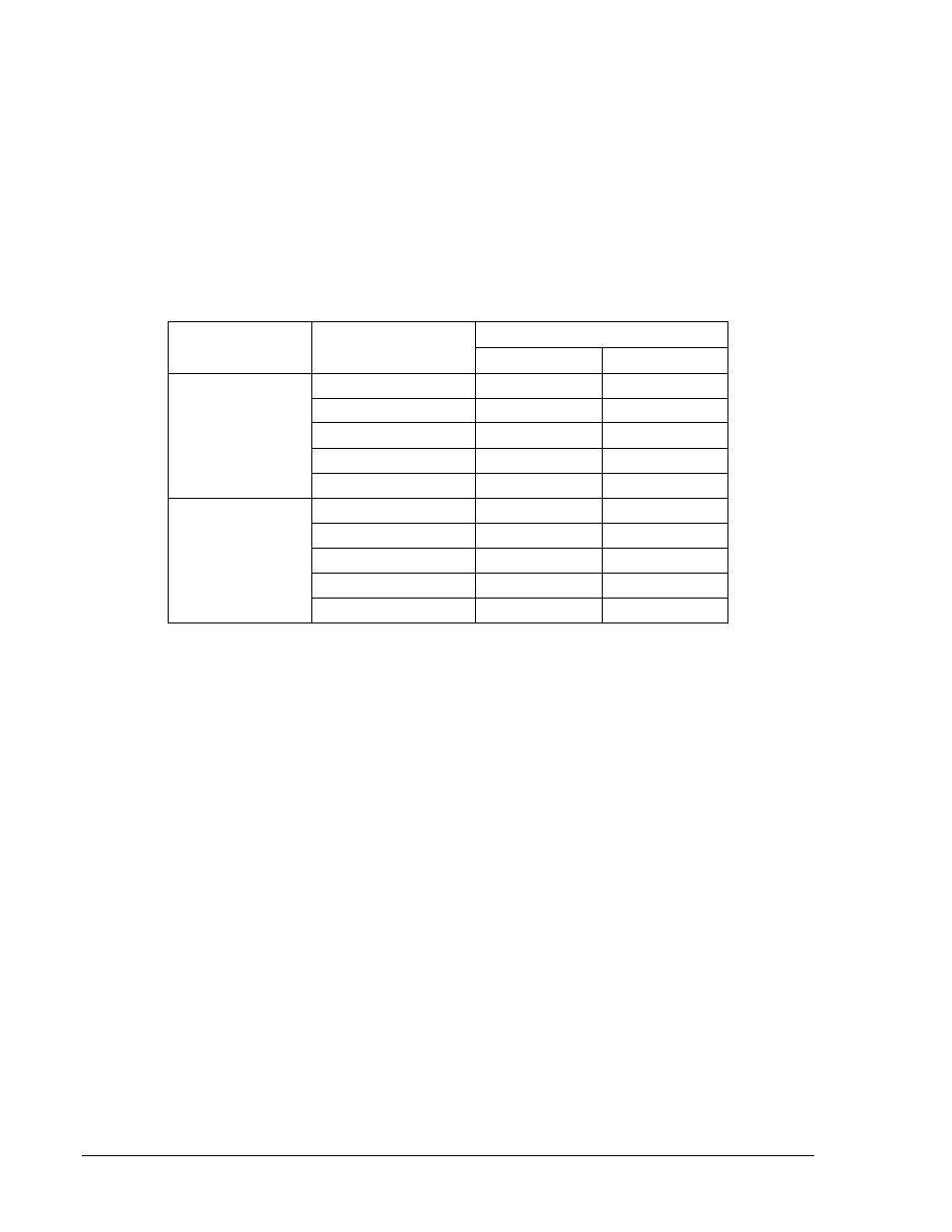
Table 13-3. Current Circuit Verification Values
Sensing Type
Applied Current
Measured Current
Lower Limit
Upper Limit
1 A
0.25 Aac
0.2475 Aac
0.2525 Aac
1 Aac
0.99 Aac
1.01 Aac
2 Aac
1.98 Aac
2.02 Aac
3 Aac
2.97 Aac
3.03 Aac
4 Aac
3.96 Aac
4.04 Aac
5 A
1 Aac
0.99 Aac
1.01 Aac
5 Aac
4.95 Aac
5.05 Aac
10 Aac
9.90 Aac
10.10 Aac
15 Aac
14.85 Aac
15.15 Aac
20 Aac
19.80 Aac
20.20 Aac
Step 3: To verify IP and IG, connect a suitably sized jumper wire across relay Terminals D2 and D3, D4
and D5, and D6 and D7. Apply an ac current source to Terminals D1 and D8.
Step 4: Apply the appropriate current values in Table 13-3 to the relay. Verify current measuring
accuracy by transmitting the M command to the relay for each applied current value. HMI
Screens 3.5 and 3.6 also can be used to verify current measurements. Screen 3.7, IN, will read
3 times the phase value.
Step 5: Leave current circuit connected and de-energized. These test connections will be used later
when verifying power readings.
Three-Phase Voltage Circuit Verification (BE1-700V)
Step 1: Connect an ac voltage source at nominal frequency between relay Terminals C13 (A-phase)
and C16 (Neutral Terminal). Apply 100 volts and verify voltage-measuring accuracy by
transmitting the M command to the relay. Readings should be: M-VA = 100 volts, M-VAB = 100
volts, M-VCA = 100 volts, M-3V0 = 100 volts, and M-V2 = 33.4 volts (applied divided by 3), all at
±1.0%. HMI Screens 3.1, 3.2, and 3.4 can also be monitored to verify voltage measurements.
Step 2: Connect an ac voltage source at nominal frequency between relay Terminals C14 (B-phase)
and C16 (Neutral Terminal). Apply 100 volts and verify voltage-measuring accuracy by
transmitting the M command to the relay. Readings should be: M-VB = 100 volts, M-VAB = 100
volts, M-VBC = 100 volts, M-3V0 = 100 volts, and M-V2 = 33.4 volts (applied divided by 3), all at
±1.0%. HMI Screens 3.1, 3.2, and 3.4 can also be monitored to verify voltage measurements.
Step 3: Connect an ac voltage source at nominal frequency between relay Terminals C15 (C-phase)
and C16 (Neutral Terminal). Apply 100 volts and verify voltage-measuring accuracy by
transmitting the M command to the relay. Readings should be: M-VC = 100 volts, M-VBC = 100
volts, M-VCA = 100 volts, M-3V0 = 100 volts, and M-V2 = 33.4 volts (applied divided by 3), all at
±1.0%. HMI Screens 3.1, 3.2, and 3.4 can also be monitored to verify voltage measurements.
13-6
BE1-700 Testing and Maintenance
9376700990 Rev M