Table 13-42. 27p uv inhibit pickup settings -29, Ng table 13-42 – Basler Electric BE1-700 User Manual
Page 325
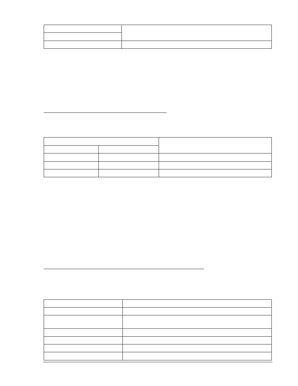
Table 13-42. 27P UV Inhibit Pickup Settings
Phase Inhibit Pickup Settings
Purpose
Undervoltage
S0-27P=96,50ms,50
Sets 27P PU at 96 V, Time Dial at minimum, UV Inhibit at 50 V.
Step 11: Using the same test connections as Step 4 above, slowly decrease the A-phase voltage until
OUT1 closes. Pickup should occur within
±2 percent or 1 volt of the 27P pickup setting.
Step 12: Continue to decrease the voltage until OUT1 opens. UV inhibit pickup should occur within
±3
percent of 50 V. Increase the voltage until OUT1 closes. UV inhibit dropout should occur at
±5
percent of inhibit pickup.
Step 13: (Optional.) Repeat Steps 1 and 2 for 127P.
Step 14: (Optional.) Repeat Steps 1 through 3 for Setting Group 1.
Phase Undervoltage and Overvoltage Timing Verification
Step 1: Using Table 13-43 as a guide, transmit the first row of setting commands to the relay.
Table 13-43. 27P and 59P Pickup and Time Delay Settings
Phase Pickup and Time Delay Settings
Purpose
Undervoltage
Overvoltage
S0-27P=72,2s
S0-59P=156,2s
Sets 27P PU at 72 V, 59P at 156 V, TD at 2 sec
S0-27P=,5s
S0-59P=,5s
Sets 27P PU at 72 V, 59P at 156 V, TD at 5 sec
S0-27P=,10s
S0-59P=,10s
Sets 27P PU at 72 V, 59P at 156 V, TD at 10 sec
Step 2: Prepare to monitor the 27P and 59P timings. Timing accuracy is verified by measuring the
elapsed time between a sensing voltage change and OUT1 closing.
Step 3: Connect and apply a 120 Vac, three-phase voltage source to Terminals C13 (A-phase), C14 (B-
phase), C15 (C-phase), and C16 (neutral). Refer to Figure 12-4 for terminal locations.
Step 4: Step the A-phase voltage down to 68 volts. Measure the time delay and verify the accuracy of
the 27P time delay setting. Timing accuracy is
±5 percent or ±3 cycles of the time delay setting.
Step 5: Step the A-phase voltage up to 165 volts. Measure the time delay and verify the accuracy of the
59P time delay setting. Timing accuracy is
±5 percent or ±3 cycles of the time delay setting.
Step 6: Repeat Steps 5 and 6 for the middle and upper time delay settings of Table 13-43.
Step 7: (Optional.) Repeat Steps 2 through 6 for the B-phase and C-phase voltage inputs.
Step 8: (Optional.) Repeat Steps 2 through 7 for Setting Group 1.
Auxiliary Undervoltage and Overvoltage Pickup Verification (3V0 VT Input)
Step 1: Prepare the 27X and 59X/159X pickup function for testing by transmitting the commands in
Table 13-44 to the relay. Reset targets.
Table 13-44. 27X and 59X/159X Pickup Test Commands
Command
Purpose
A=
Gains write access.
SL-N=NONE
Zero out custom logic settings. Overwrite with LOGIC=NONE
settings.
Y
Confirm overwrite.
SL-N=27X/59/159X
Sets 27X/59/159X as custom logic name.
SL-27X=2,0
Enables 27X (3E0), disables blocking.
SL-59X=2,0
Enables 59X, disables blocking.
9376700990 Rev M
BE1-700 Testing and Maintenance
13-29