Table 13-37. v/hz reset time -27, N table 13-37 – Basler Electric BE1-700 User Manual
Page 323
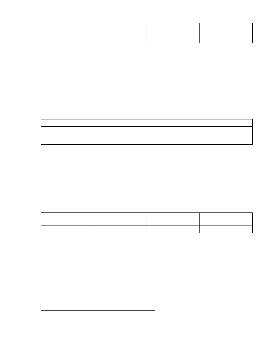
Table 13-37. V/Hz Reset Time
Percent of Nominal
V/Hz
Time Dial 0.5
Time Dial 1.0
Time Dial 2.0
120%
12.5 seconds
25 seconds
50 seconds
Step 4: Repeat Step 3 for Trip Time Dial 1.0 and 2.0 (½ trip time is approximately 12.5 seconds for
Time Dial 1.0, and 25 seconds for Time Dial 2.0. (Still reapply voltage after 5 seconds as reset
time dial is still 0.2.)
Step 5: (Optional.) Repeat Steps 2 through 4 for the B-phase and C-phase voltage inputs.
Step 6: (Optional.) Repeat Steps 2 through 5 for Setting Group 1.
Overexcitation, Volts/Hertz Definite Time (24D)Trip Time Verification
The following test uses the (M-1)^2 time curve.
Step 1: Using Table 13-38 as a guide, transmit the setting commands to the relay.
Table 13-38. Definite Time V/Hz Trip Time Settings
Settings
Purpose
S0-24D=2.36,50ms,0.0,50ms
Sets the first 24 definite pickup at 118% of nominal (2.36 V/Hz) and
definite time delay at minimum. Sets second pickup at 0 and time
delay at minimum.
Step 2: Connect a 120 Vac, three-phase, 50 or 60-hertz voltage source (depending on user's nominal
frequency) to Terminals C13 (A-phase), C14 (B-phase), C15 (C-phase), and C16 (neutral).
Refer to Figure 12-4 for terminal locations.
Step 3: Definite timing tests are based on % of nominal Volts/Hertz (1 PU value). Apply A-phase voltage
at nominal frequency and a value of voltage that equals the V/Hz % of nominal shown in Table
13-53 (118% or 2.36 V/Hz). Measure the time between the application of voltage and the
closure of OUT1. Verify that the relay operates within
±0.5% or 1 cycle, whichever is greater, for
the TD settings shown in Table 13-39.
Table 13-39. Definite Time (24D) V/Hz Trip Times
Percent of Nominal
V/Hz
Time Dial 0.5
Time Dial 1.0
Time Dial 2.0
118%
0.50 seconds
5 seconds
20 seconds
Step 4: (Optional.) Repeat Steps 2 through 4 for the B-phase and C-phase voltage inputs.
Step 5: (Optional.) Repeat Steps 2 through 5 for Setting Group 1.
Step 6: Set first definite time pickup setting to 0 and set the second definite time pickup setting to 2.36
V/Hz.
Step 7: Repeat Steps 2 through 5 for the second definite time function.
Phase and Auxiliary Undervoltage/Overvoltage (27/59) (BE1-700V)
Purpose: To verify the operating accuracy of the 27P/127P/27X and 59P/159P/59X/159X protection
elements.
Reference Commands: SL-27P/127P/27X, SL-59P/159P/59X/159X, SL-VO, SL-GROUP, RG-STAT
Phase Undervoltage and Overvoltage Pickup Verification
Step 1: Prepare the 27P and 59P pickup functions for testing by transmitting the commands in Table
13-40 to the relay. Reset targets. Follow the same procedure for the 127P/159P except for the
27/127 under voltage inhibit pickup test.
9376700990 Rev M
BE1-700 Testing and Maintenance
13-27