Table 13-25. 51p/51n/51q timing values -22, Table 13-26. 51p/51n/51q pickup test commands -22 – Basler Electric BE1-700 User Manual
Page 318
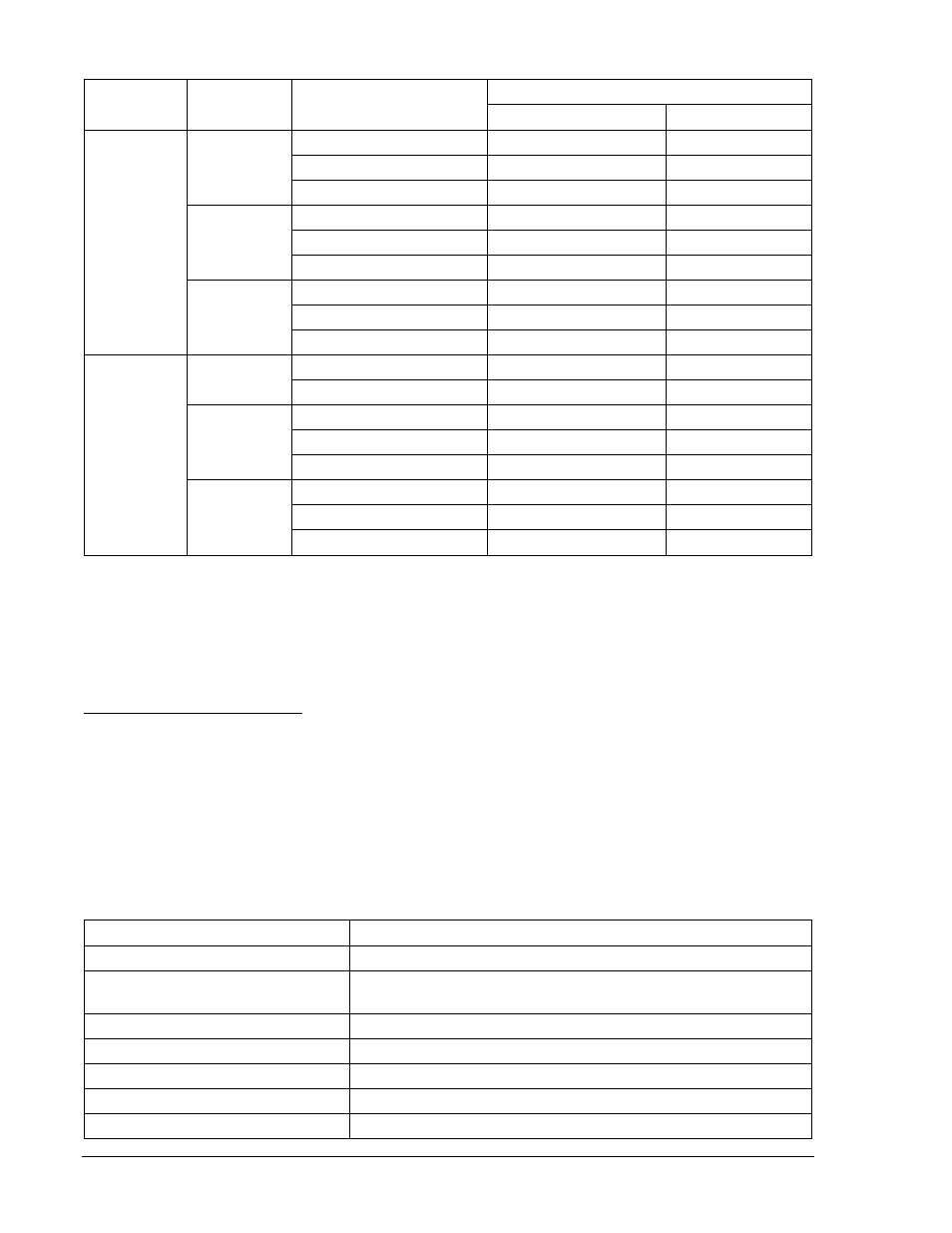
Table 13-25. 51P/51N/51Q Timing Values
Sensing
Type
Time Dial
Applied Current
Relay Trip Limits
Lower Limit
Upper Limit
1 A
0.5
0.15 Aac
0.748 s
0.827 s
0.50 Aac
0.190 s
0.240 s
2.5 Aac
0.100 s
0.150 s
5
0.15 Aac
7.244 s
8.007 s
0.50 Aac
1.798 s
1.988 s
2.5 Aac
0.944 s
1.044 s
9.9
0.15 Aac
14.318 s
15.825 s
0.50 Aac
3.535 s
3.907 s
2.5 Aac
1.844 s
2.038 s
5 A
0.5
2.5 Aac
0.190 s
0.240 s
12.5 Aac
0.100 s
0.150 s
5
0.75 Aac
7.244 s
8.007 s
2.5 Aac
1.798 s
1.988 s
12.5 Aac
0.944 s
1.044 s
9.9
0.75 Aac
14.318 s
15.825 s
2.5 Aac
3.535 s
3.907 s
12.5 Aac
1.844 s
2.038 s
Step 4: Repeat Steps 2 and 3 for all of the current and time dial settings for your current sensing type.
Step 5: (Optional.) Repeat Steps 2 through 4 for phase B (Terminals D3 and D4) and phase C
(Terminals D5 and D6).
Step 6: (Optional.) Using ASCII commands, substitute 151 for any 51 logic or setting commands in each
test.
Pickup and Dropout Verification
Purpose: To verify the pickup accuracy of the 51P, 51N, 151P, 151N, and 51Q elements.
Reference Commands: SL-51P, SL-151P, SL-51N, SL-51Q, SL-151N, SL-GROUP, SL-VO
Step 1: Connect a current source to Terminals D1 and D2 (A-phase). Refer to Figure 12-3 for
terminal locations. An ohmmeter or continuity tester may be used to monitor output contact
status.
Step 2: To prepare the 51P, 51N, and 51Q elements for testing, transmit the commands in Table 13-26
to the relay. Reset targets.
Table 13-26. 51P/51N/51Q Pickup Test Commands
Command
Purpose
A=
Gains write access.
SL-N=NONE
Zero out custom logic settings. Overwrite with LOGIC=NONE
settings.
Y
Confirm overwrite.
SL-N=PU51
Sets PU51 as custom logic name.
SL-51P=1,0
Enables 51P and disables blocking.
SL-51N=1,0
Enables 51N and disables blocking.
SL-51Q=1,0
Enables 51Q and disables blocking.
13-22
BE1-700 Testing and Maintenance
9376700990 Rev M