15 mpc8572 system clock, 16 reset control logic, 15 mpc8572 system clock 4.16 reset control logic – Artesyn CPCI-6200 Installation and Use (May 2015) User Manual
Page 99: Table 4-2, System clock frequencies, Table 4-3, Reset sources, Reset, Control logic, Functional description
Functional Description
CPCI-6200 Installation and Use (6806800J66E)
99
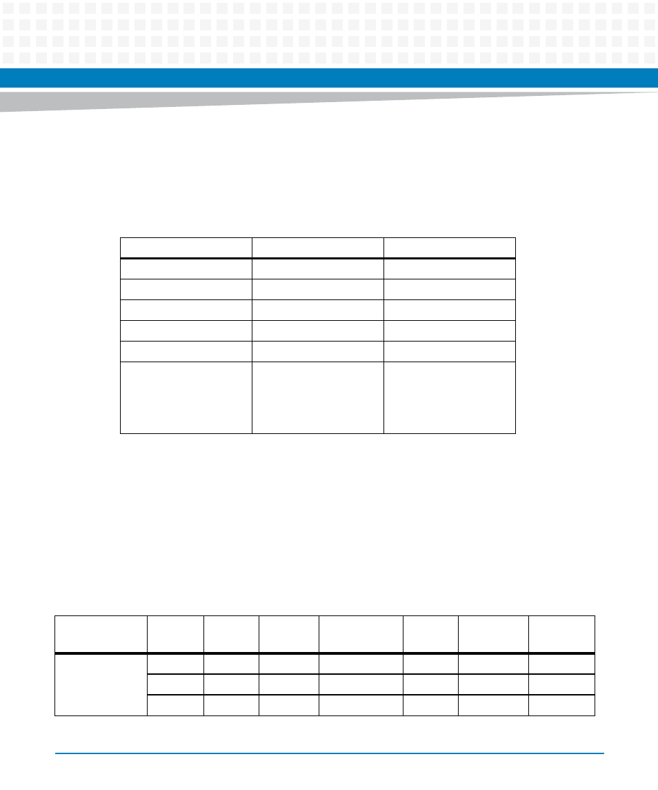
4.15 MPC8572 System Clock
An oscillator drives the MPC8572 system clock. The following table details the clock
frequencies for various processor configurations.
4.16 Reset Control Logic
There are multiple sources of reset on the CPCI-6200. The following table shows the reset
sources and their effect on board reset. The effect of each reset source depends on the board's
current status such as LRO switch setting, board in system or peripheral slot, Watchdog Control
Register value (WD_EN and SYS_RST), System Control Register value (SW_RST), CPCI Control
and Status Register value (BP_RST_MASK), etc.
Table 4-2 System Clock Frequencies
Clock/CPU Configuration
1.33 GHz CPU Blade
1.5 GHz CPU Blade
SYSCLK (a)
66.67 MHz
100 MHz
CCB (Platform) (b)
533 MHz
600 MHz
Core 0/1 (c)
1.33 GHz
1.5 GHz
DDRCLK (d)
66.66 MHz
66.66 MHz
DDR3 clock to DIMM (e)
333 MHz
400 MHz
Notes
b:a = 8:1
c:b = 5:2
e:d = 10:1
(divide by 2 internally)
b:a = 6:1
c:b = 5:2
e:d = 12:1
(divide by 2 internally)
Table 4-3 Reset Sources
Reset Source
WD_EN
SYS_RST
SW_RST
1
PB_RST_MASK
LRO SW
System Slot
Function
Power-up or Hot
Insertion
X
X
X
X
X
YES
Note 1
X
X
X
X
ON
NO
Note 1
X
X
X
X
OFF
NO
Note 2