4 rear panel connectors, 5 on-board connectors and headers, Table 5-1 – Artesyn CPCI-6200 Installation and Use (May 2015) User Manual
Page 110: Cpci-6115-mcptm rear panel connectors, Table 5-2, On-board connectors and headers, Transition module preparation and installation
Transition Module Preparation and Installation
CPCI-6200 Installation and Use (6806800J66E)
110
5.4
Rear Panel Connectors
The rear panel port connectors on the CPCI-6115-MCPTM are listed in
and shown in
for connector pinout information.
5.5
On-Board Connectors and Headers
The following table lists the connectors and headers on the CPCI-6115-MCPTM. Use the links
in the Location column to find the connector descriptions and pin assignments or jumper
settings.
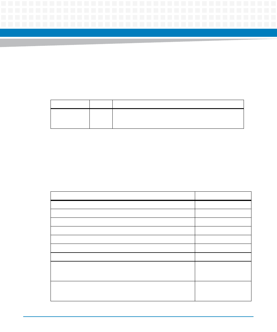
Table 5-1 CPCI-6115-MCPTM Rear Panel Connectors
Type
Number
Description
Serial Ports
J25
Routed to four RJ-45 connectors for COM1, COM2, COM3, and
COM4 connections (MXP version). Note: COM3 and COM4 are
not used.
Table 5-2 On-Board Connectors and Headers
Connector/Header
Location
CPCI-6115-MCPTM IDE CompactFlash Connector (J1)
CPCI-6115-MCPTM PMC I/O Module 1 - Host I/O Connector (J10)
CPCI-6115-MCPTM PMC I/O Module 2 - Host I/O Connector (J20)
CPCI-6115-MCPTM PMC I/O Modules 1 & 2 - PMC I/O (J14/J24)
CPCI-6115-MCPTM CompactPCI User I/O Connector (J3)
CPCI-6115-MCPTM CompactPCI User I/O Connector (J5)
CPCI-6115-MCPTM 10/100/1000BaseTx Connectors
COM1 Header (J6)
COM1 and COM2
Asynchronous Serial Ports
Jumpers
COM2 Header (J11)