4 compactpci user i/o connector, Table 5-8, User i/o connector pinout, j5 – Artesyn CPCI-6200 Installation and Use (May 2015) User Manual
Page 118: Transition module preparation and installation
Transition Module Preparation and Installation
CPCI-6200 Installation and Use (6806800J66E)
118
*Not connected on MXP version
5.5.4
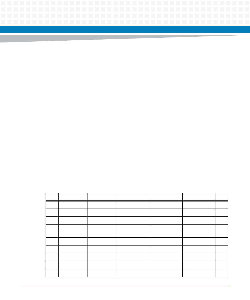
CompactPCI User I/O Connector
Connector J5 is a 110 pin AMP Z-pack 2mm hard metric type B connector. This connector
routes the I/O signals for the PMC2 I/O signals, the IDE port, four asynchronous serial ports and
I2C. The pin assignments for J5 on the processor board and the CPCI-6115-MCPTM are as
follows:
(Outer row F is assigned and used as ground pins but is not shown in the table).
Signal Description
PMCIO:
PMC1IO(64:1)
PMC1 I/O signals 1 through 64
Ethernet:
PORTn_TXP
high side of differential transmit data
PORTn_TXN
low side of differential transmit data
PORTn_RXP
high side of differential receive data
PORTn_RXN
low side of differential receive data
Table 5-8 User I/O Connector Pinout, J5
Pin
Row A
Row B
Row C
Row D
Row E
Pin
22
DRESET_L
COM4_TXD
COM3_TXD
COM2_TXD
COM1_TXD
22
21
INTRQA
COM4_RXD
COM3_RXD
COM2_RXD
COM1_RXD
21
20
CS1FXA_L
CS3FXA_L
DA2
MXDI
MXDO
20
19
Not
Connected
DIORDYA
DA1
MXCLK
MXSYNC#
19
18
DIOWA_L
DA0
TMCOM1_L
I2C_CLK
I2C_DATA
18
17
GND
DD14
DD15
DIORA_L
Not Connected
17
16
DD9
DD10
DD11
DD12
DD13
16
15
DD5
DD6
GND
DD7
DD8
15
14
DD0
DD1
DD2
DD3
DD4
14