7 pci/pci-x configuration, Table 8-59, I2c bus device addressing – Artesyn CPCI-6200 Installation and Use (May 2015) User Manual
Page 223
Memory Maps and Addresses
CPCI-6200 Installation and Use (6806800J66E)
223
8.7
PCI/PCI-X Configuration
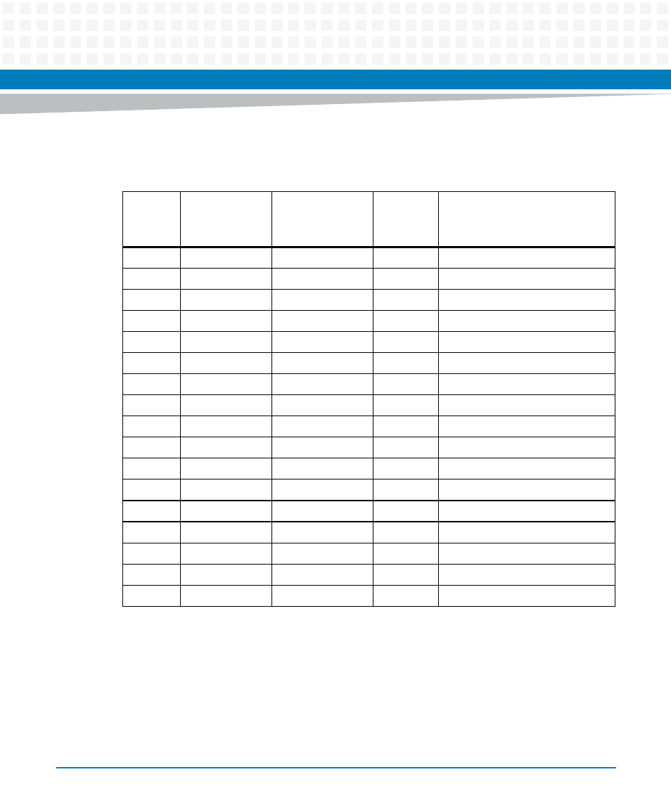
The following sections detail the PCI/PCI-X configuration of the onboard PCI devices.
Table 8-59 I
2
C Bus Device Addressing
I
2
C Bus
I
2
C Bus Address
Device Address
A2 A1 A0
(binary)
Size
(bytes)
Function
Bus 4
0xA0
000
N/A
Reserved
0xA2
001
256 x 8
DDR3 memory bank 1 SPD
1
1. Each SPD defines the physical attributes of each bank of memory.
0xA4
010
256 x 8
DDR3 memory bank 2 SPD
1
0xA6
011
64K x 8
User configuration 1
0xA8 / 0xAA
100
512 x 8
RTM VPD (off-board configuration)
0xAC
110
64K x 8
User configuration 2
0xAE
111
8K x 8
VPD (on-board configuration)
0xD0
N/A
N/A
M41T83 real-time clock
Bus 3
0x4C or 0x98
NA
N/A
ADT7461 temperature sensor
0xA0
000
64K x 8
User configuration
0xA2
001
64K x 8
VPD (on-board configuration)
0xA4
010
64K x 8
System Event Log (SEL)
0xA6
011
Reserved
0xA8
100
Reserved
0xAA
101
Reserved
0xAC
110
Reserved
0xAE
111
Reserved
- ARTM-9405 16x10GbE Installation and Use Guide (May 2014) (64 pages)
- ATCA 7370 / ATCA 7370-S Installation and Use (January 2015) (256 pages)
- ATCA 7370 / ATCA 7370-S Installation and Use (September 2014) (254 pages)
- ARTM-831X Installation and Use (June 2014) (346 pages)
- ATCA-7350 - Integrating with Workbench User Guide (September 2014) (34 pages)
- ATCA-7350 Installation and Use (September 2014) (208 pages)
- ATCA-7365-CE Installation and Use (Jan 2015) (300 pages)
- ATCA-7365-CE Installation and Use (May 2014) (294 pages)
- ATCA-7365-CE Installation and Use (May 2014) (306 pages)
- ATCA-7368 Installation and Use (June 2014) (222 pages)
- ATCA-7475 Installation and Use (October 2014) (284 pages)
- ATCA-7480 Installation and Use (April 2015) (330 pages)
- ATCA-8330 Installation and Use (April 2015) (236 pages)
- ATCA-8320 Installation and Use (May 2014) (456 pages)
- ATCA-9305 User's Manual (May 2014) (270 pages)
- ATCA-9405 Installation and Use (October 2014) (168 pages)
- ATCA-F120 Installation and Use (August 2014) (122 pages)
- ATCA-F140 Installation and Use (September 2014) (138 pages)
- ATCA-MF106 Installation and Use (September 2014) (86 pages)
- Centellis-4440/AXP1440 Installation and Use (September 2014) (208 pages)
- Centellis 4410 (AXP-1410) Installation and Use (July 2014) (202 pages)
- Centellis 2100 Release 3.0 Installation and Use (March 2015) (192 pages)
- Centellis 2100 Release 3.0 Installation and Use (March 2015) (176 pages)
- Centellis 2000 User Card-10GE Installation and Use (May 2014) (54 pages)
- Centellis 2000 User Card-10GE with Telco Alarm Installation and Use (May 2014) (60 pages)
- COMX-CAR-210 Installation and Use (August 2014) (76 pages)
- COMX-P1022 Installation and Use (July 2014) (84 pages)
- COMX-P2020 Installation and Use (February 2015) (100 pages)
- COMX-CORE Series Installation and Use (August 2014) (128 pages)
- COMX-P2020 Installation and Use (July 2014) (100 pages)
- COMX-P4080-2G-ENP2 Installation and Use (August 2014) (70 pages)
- COMX-P4080 Installation and Use (August 2014) (126 pages)
- COMX-P40x0 ENP2 Installation and Use (August 2014) (130 pages)
- COMX-P40x0 ENP2 Installation and Use (January 2015) (140 pages)
- iVPX7225 RTM Installation and Use (April 2015) (56 pages)
- MITX-430/MITX-440-DVI-2E Installation and Use (August 2014) (118 pages)
- SCP-MITX-CORE-820-SM Installation and Use (August 2014) (132 pages)
- iVPX7225 Installation and Use (April 2015) (168 pages)
- MVME2502 Installation and Use (August 2014) (150 pages)
- MVME2502 Installation and Use (December 2014) (166 pages)
- MVME2500 VxWorks 6.8 AMP User Guide (August 2014) (40 pages)
- MVME2500 VxWorks 6.8 User Guide (April 2014) (44 pages)
- MVME3100 Single Board Computer Installation and Use (June 2014) (156 pages)
- MVME4100 Single Board Computer Installation and Use (June 2014) (136 pages)