7 functional description, 1 ide flash, Figure 5-4 – Artesyn CPCI-6200 Installation and Use (May 2015) User Manual
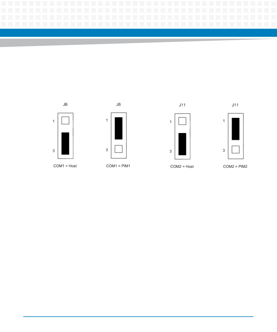
Page 124: Com1 and com2 serial port jumpers (j6/j11)
Transition Module Preparation and Installation
CPCI-6200 Installation and Use (6806800J66E)
124
to either the processor board front panel or through the PIM2 socket on the transition module.
When pins 1 and 2 are jumpered on J11, the COM2 signal is routed to PIM2 on the transition
module. When pins 2 and 3 are jumpered on J11, the COM2 signal is routed to the processor
board front panel.
5.7
Functional Description
The following subsections describe the major functional components of the CPCI-6115-
MCPTM transition module. There are certain differences between the IP version and the
CompactPCI model that are explained in the subsections where those differences apply.
5.7.1
IDE Flash
The CPCI-6200 SBC supports a single IDE channel routed to the J5 User I/O connector. The
CPCI-6115-MCPTM contains one 50-pin Type II connector which supports a removable IDE
CompactFlash memory card on the primary IDE channel. Refer to the
for the definition of this connector. The CompactFlash connector is not accessible
through the rear panel. The CPCI-6200 transition module must be removed in order to install
a CompactFlash memory card.
Figure 5-4
COM1 and COM2 Serial Port Jumpers (J6/J11)