Clock switchover parameter settings, Clock switchover parameter settings -3 – Altera MAX 10 Clocking and PLL User Manual
Page 69
Clock Switchover Parameter Settings
The parameter settings for clock switchover feature are located on the Clock switchover page of the
ALTPLL IP core parameter editor.
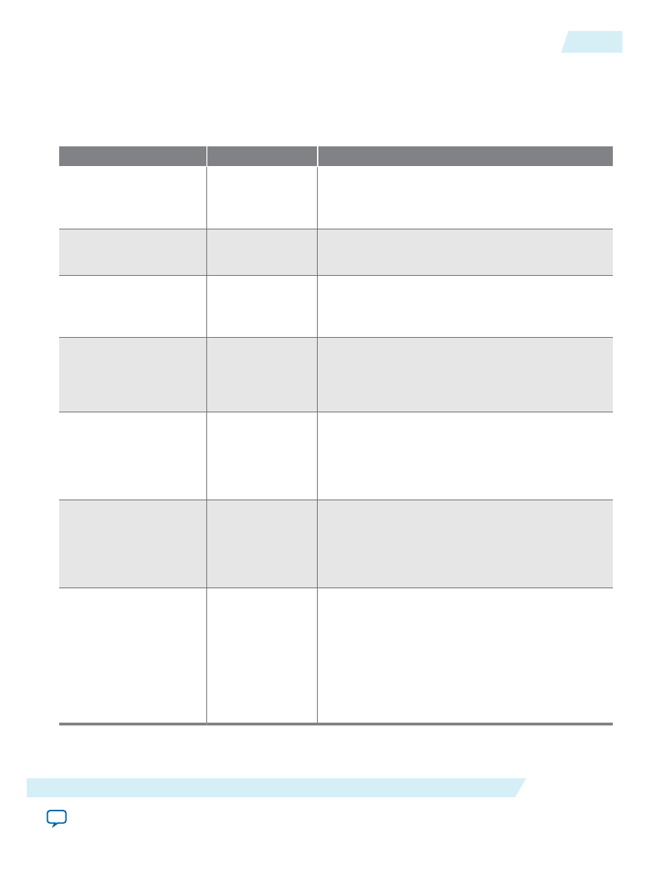
Table 6-3: Clock Switchover Parameter Editor Settings
Parameter
Value
Description
Create an 'inclk1' input
for a second input clock
On or Off
Turn on this option to enable the switchover feature.
The
inclk0
signal is by default the primary input clock
signal of the ALTPLL IP core.
Create a 'clkswitch'
input to manually select
between the input clocks
—
Select this option for manual clock switchover mode.
Allow PLL to automati‐
cally control the
switching between input
clocks
—
Select this option for automatic clock switchover mode.
The automatic switchover is initiated during loss of lock
or when the
inclk0
signal stops toggling.
Create a 'clkswitch'
input to dynamically
control the switching
between input clocks
On or Off
Turn on this option for automatic clock switchover
with manual override mode.
The automatic switchover is initiated during loss of lock
or when the
clkswitch
signal is asserted.
Perform the input clock
switchover after
(number) input clock
cycles
On or Off
Turn on this option to specify the number of clock
cycles to wait before the PLL performs the clock
switchover.
The allowed number of clock cycles to wait is device-
dependent.
Create an 'activeclock'
output to indicate the
input clock being used
On or Off
Turn on this option to monitor which input clock
signal is driving the PLL.
When the current clock signal is
inclk0
, the
activeclock
signal is low. When the current clock
signal is
inclk1
, the
activeclock
signal is high.
Create a 'clkbad' output
for each input clock
On or Off
Turn on this option to monitor when the input clock
signal has stopped toggling.
The
clkbad0
signal monitors the
inclk0
signal. The
clkbad1
signal monitors the
inclk1
signal.
The
clkbad0
signal goes high when the
inclk0
signal
stops toggling. The
clkbad1
signal goes high when the
inclk1
signal stops toggling. The
clkbad
signals
remain low when the input clock signals are toggling.
Related Information
•
UG-M10CLKPLL
2014.12.15
Clock Switchover Parameter Settings
6-3
ALTPLL IP Core References
Altera Corporation